Kenwood TK-431 Filter Changeout
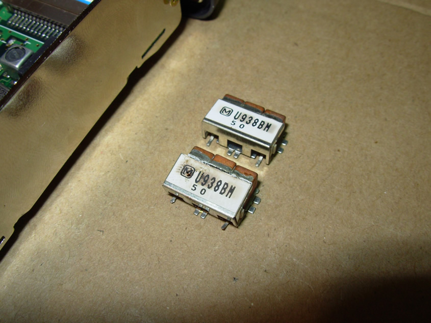
If you are interested in changing out the filters on your Kenwood TK-431 for the purpose of making the radio into a repeater receiver or just want to get a little extra out of the receiver this is easily accomplished! The existing receive filters in a TK-431 are 3 pole SMD type centered at 938MHz and have a bandwidth of 6MHz; meaning they are intended to pass frequencies from 935 to 941MHz. At 927MHz they start to exhibit attenuation, they do NOT need to be changed for use at 927MHz. At 902MHz RX they are going to exhibit a very large amount of attenuation- making changeout of the RX filters quite necessary. There are 2 types of filters that work best for installation into the TK-431. The Toko 4DFB-915E-10 SMD filters are almost a drop in replacement and the thru-hole mounted muRata DFC2R915P025BTD filters also work very well with a little creativity in how you mount them. The Toko 4DFB-915E-10 SMD filters and the muRata DFC2R915P025BTD filters I have found to work the best in the TK-431, however, there is no doubt that other filter styles and types can also be made to fit. Before removing the old filters its best to ensure that the filters you want to install will fit in the space on the RF board and that they have a bandwidth that will cover the frequencies you intend to receive.
To change out the receive filters on the TK-431 you must disassemble the handheld down to the bare chassis and remove the RF shield that they reside underneath. To remove the filters from the PCB you will need to use a hot air SMD re-work station, as you can remove the filters entirely with no-damage to the traces on the RF board in around 1 to 2 minutes. A good alternative to purchasing a hot air rework station is purchasing something you can use much more frequently, a butane powered soldering iron with the diffuser (nozzle) tip attachment, I have used the Master Appliance Iron model number UT-100SI with great results; do not use anything smaller than this as it does not provide enough heat.
The filters in the Kenwood TK-431 are a lot more difficult to remove using a normal soldering iron and I would strongly suggest that this method be avoided unless a very high power soldering iron is used in the 100W to 150W range. If you use a high power soldering iron to remove the filters then be sure to take your time and heat and remove the filters section by section (in pieces).
Pictured below is step by step disassembly as well as removal of the TK-431 receive filters using my Hakko 850 Hot Air station.
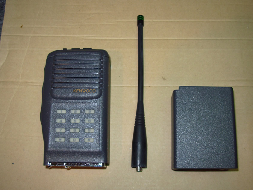
- You will first need to disassemble your TK-431 by removing the antenna and battery.
- Once the easy stuff has been removed you will need to remove the radio from the plastic housing/front panel. To remove the main radio chassis from the plastic housing/front panel you will need to remove the 3 screws that hold the chassis to the plastic housing/front panel. There are 2 large screws that need to get removed on the bottom of the radio and the negative battery terminal screw- the radio will slide out of the top of the plastic case once these screws are removed. Do NOT disassemble the radio over your nicely manicured shag rug; as there are little parts and pieces that can be lost very easily!
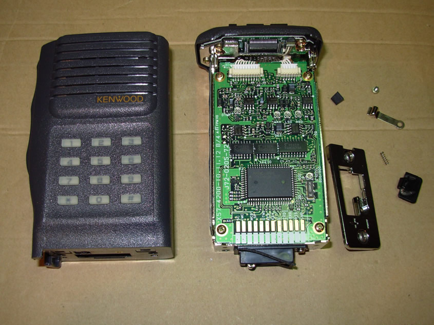
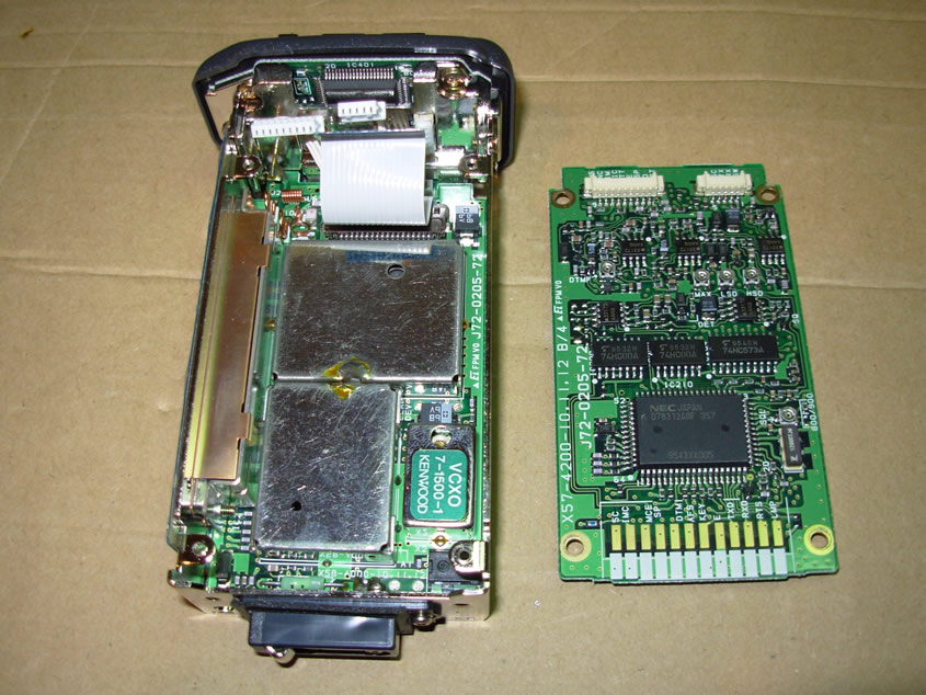
- Once the main chassis is removed from the plastic housing/front panel you will need to remove the control board from the RF section of the radio by removing the 4 screws that hold the board to the chassis and disconnecting the 2 wire harnesses (CN202 and CN203) on the top of the board and the ribbon cable (CN201) on the bottom side of the board.
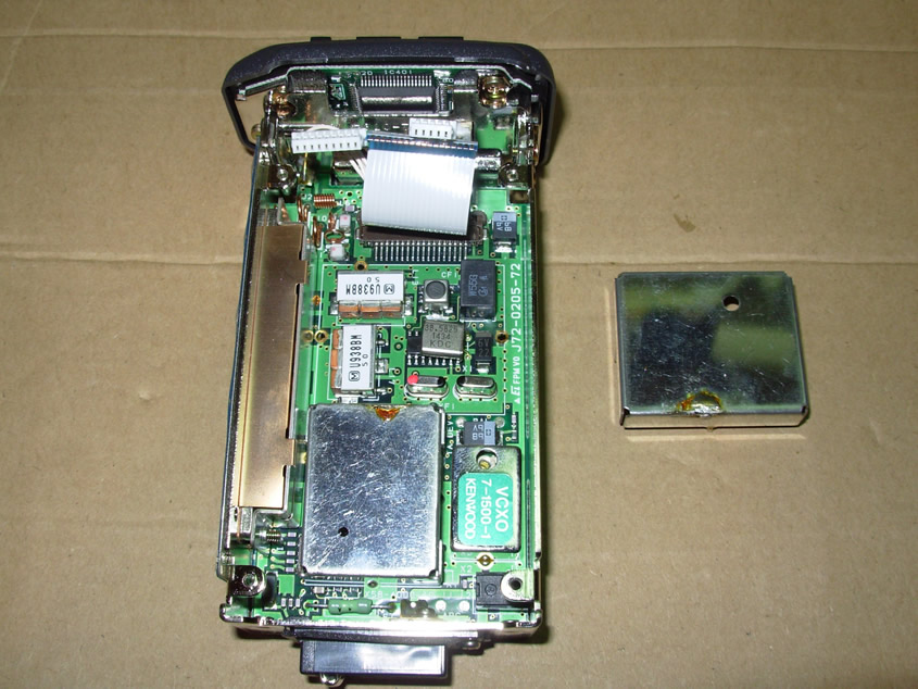
- Once the control board is removed from the RF board and main chassis the RF shield that covers the receive filters will need to be removed by de-soldering it from the RF board. You are going to remove the upper RF shield of the two shields on the RF board in relation to the battery terminals on the bottom of the radio- pictured is the RF shield removed from the RF board.
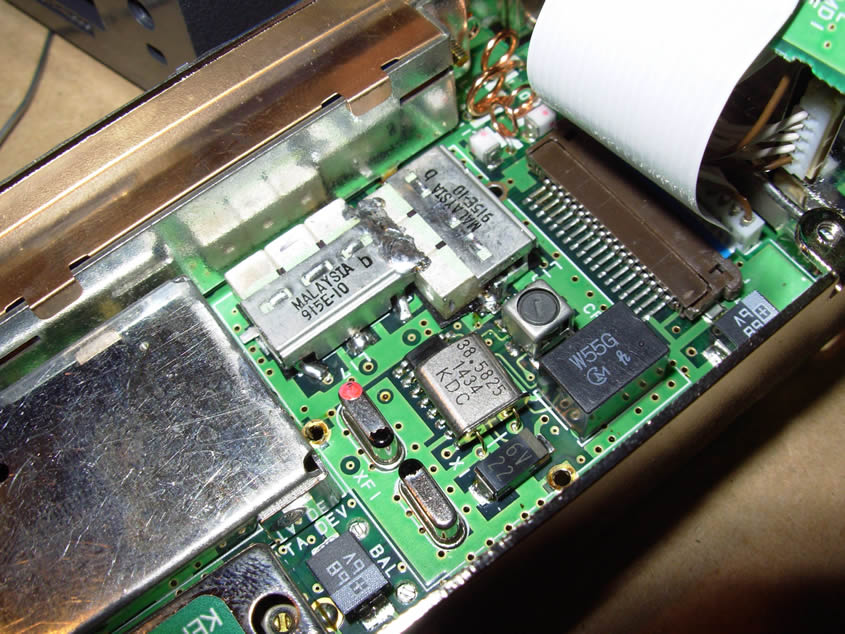
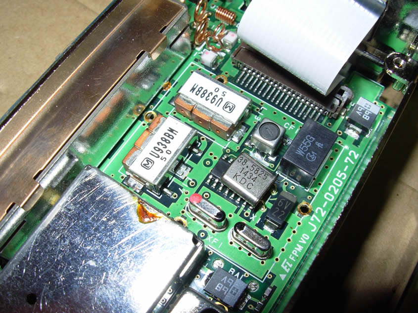
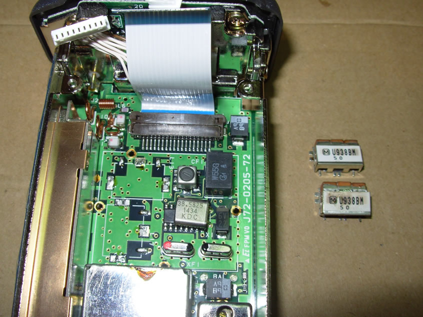
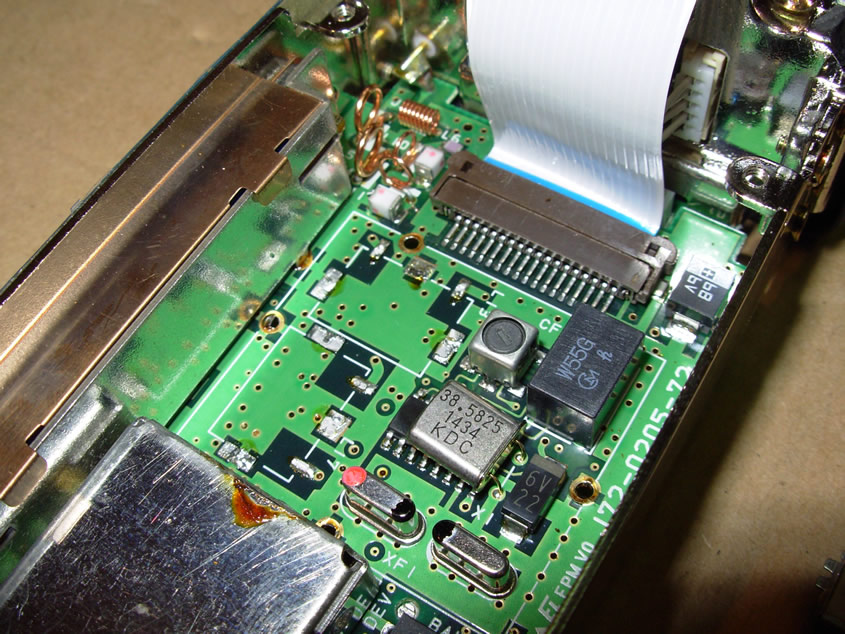
- Once the RF shield is removed we can clearly see the RX filters that will need to be removed. There is not a lot of space around the filters so when using hot air to remove the filters be very careful and take your time.
- With the filters removed be sure to clean and inspect the area around where the new filters are to be installed and also check the underside of the RF board to ensure nothing came loose or was damaged in removal of the SMD filters. Clean the area where the filters were removed with Isopropyl Alcohol of 90% or use flux remover on a Q-tip to remove any residue.
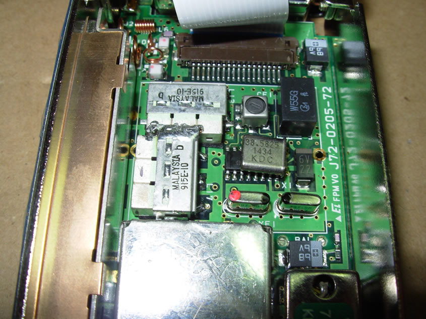
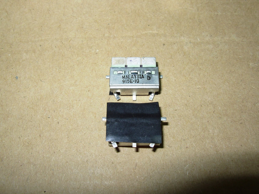
- The 3 pole 938MHz centered filters we removed will be changed out with 915MHz centered, 26MHz Bandwidth, Toko 4DFB-915E-10 SMD filters- which are almost a drop in replacement. The Toko 4DFB-915E-10 filter will require that you bend the input and output pins slightly so that they fit properly. Due to the limited space of the area where the filters are to be installed I covered the bottom of the filters with electrical tape to insulate them from the traces on the input and output terminals to the filters because the bottom of the filters will overhang the traces on the board and could potentially short them to ground. When installing these filters make sure initially that you just tack solder them in place for proper fitting and ensure that you have set aside enough space to fit them both in place. After getting them in place solder the input and output terminals. A major part of the filter installation is to ensure that you adequately ground the filter body to the PCB. Proper grounding of these filters, and all band pass filters in general, has a big impact on their proper function.
- After soldering the terminals and body to the PCB I laid a bead of solder across the filters so that they are grounded together, this was done to ensure that the filters are both adequately grounded. After installation of the filters you can start reassembling the radio. It is critical that the RF shield that covers the 3 pole receive filters be reinstalled and grounded to the shield next to it. After installation of the RF shield you can reinstall the control board and reconnect the 2 wire harnesses (CN202 and CN203) and ribbon cable (CN201) to the main RF board/chassis. After installation of the control board, install the main chassis back in the plastic housing/front panel; you should enjoy the increased RX sensitivity that your TK-431 now has!