Kenwood TK-931 for Repeater Use
The TK-931 as a Repeater Receiver
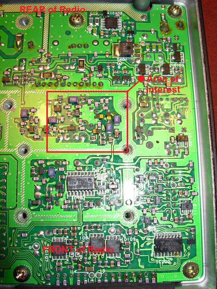
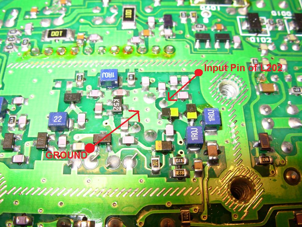
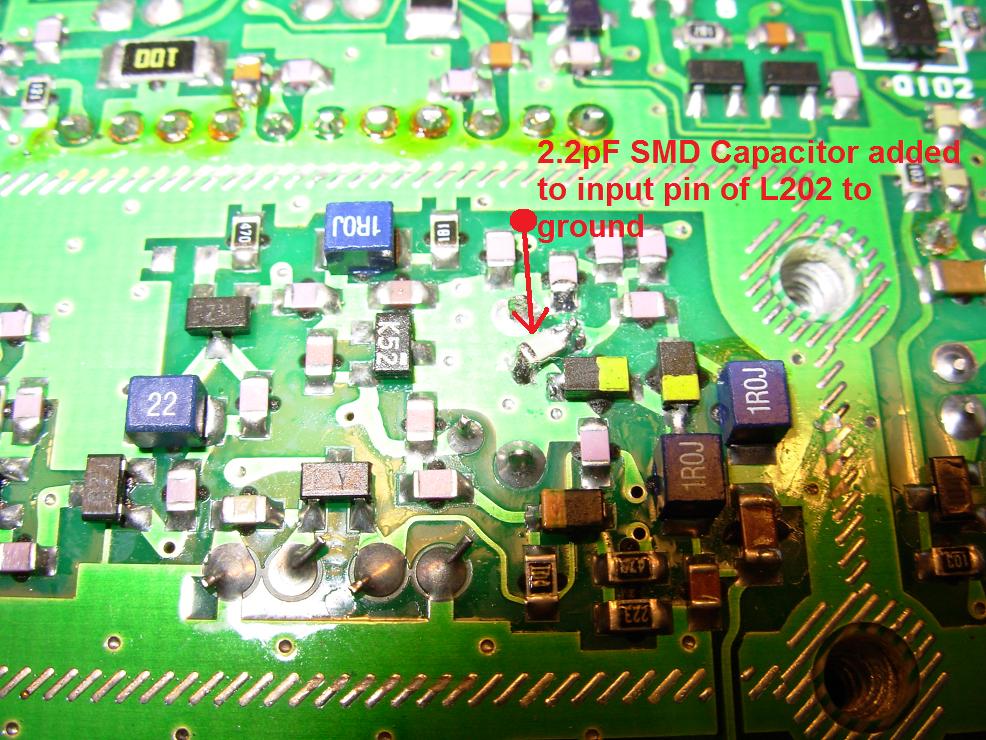
The TK-931’s make an excellent repeater receiver or link radio. If you would like to use any model TK-931 as a repeater receiver the VCO will require one small modification. The modification requires the addition of a 2.2pF or 3pF ceramic disk or surface mount capacitor. This value capacitor will allow the VCO to function on receive from 902 up to ~907MHz, adding more capacitance allows the VCO to receive higher in the band. Pictured below is where to add the capacitor.
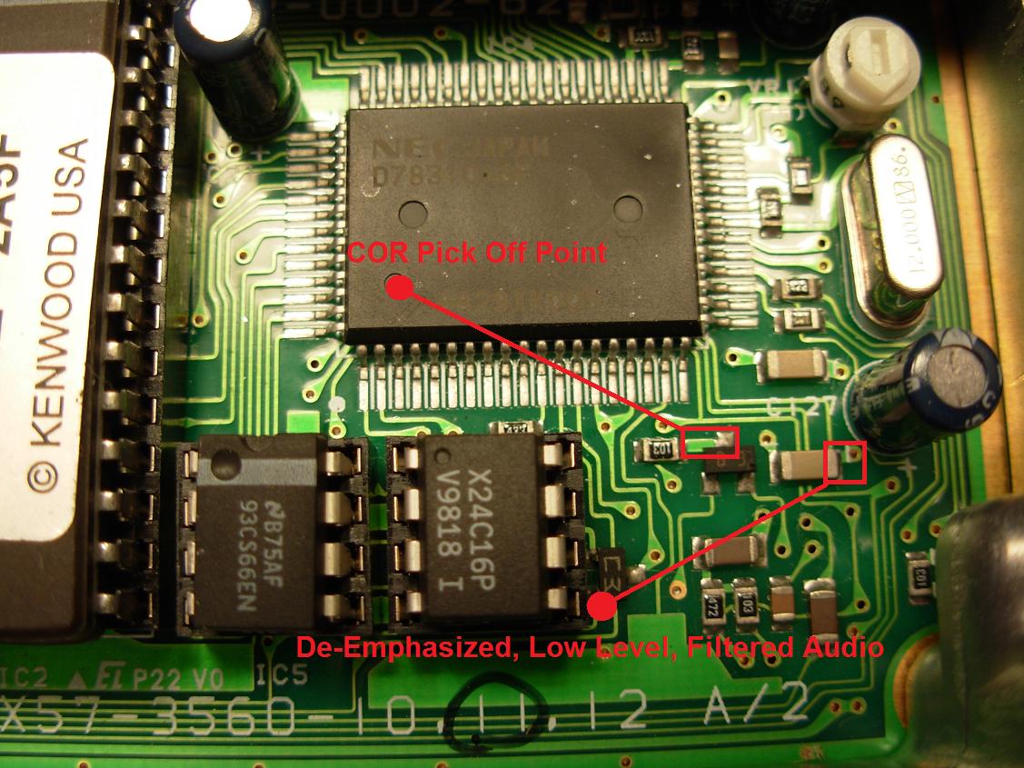
The pick off points for COR and low level, filtered, de-emphasized audio can be found pictured below.
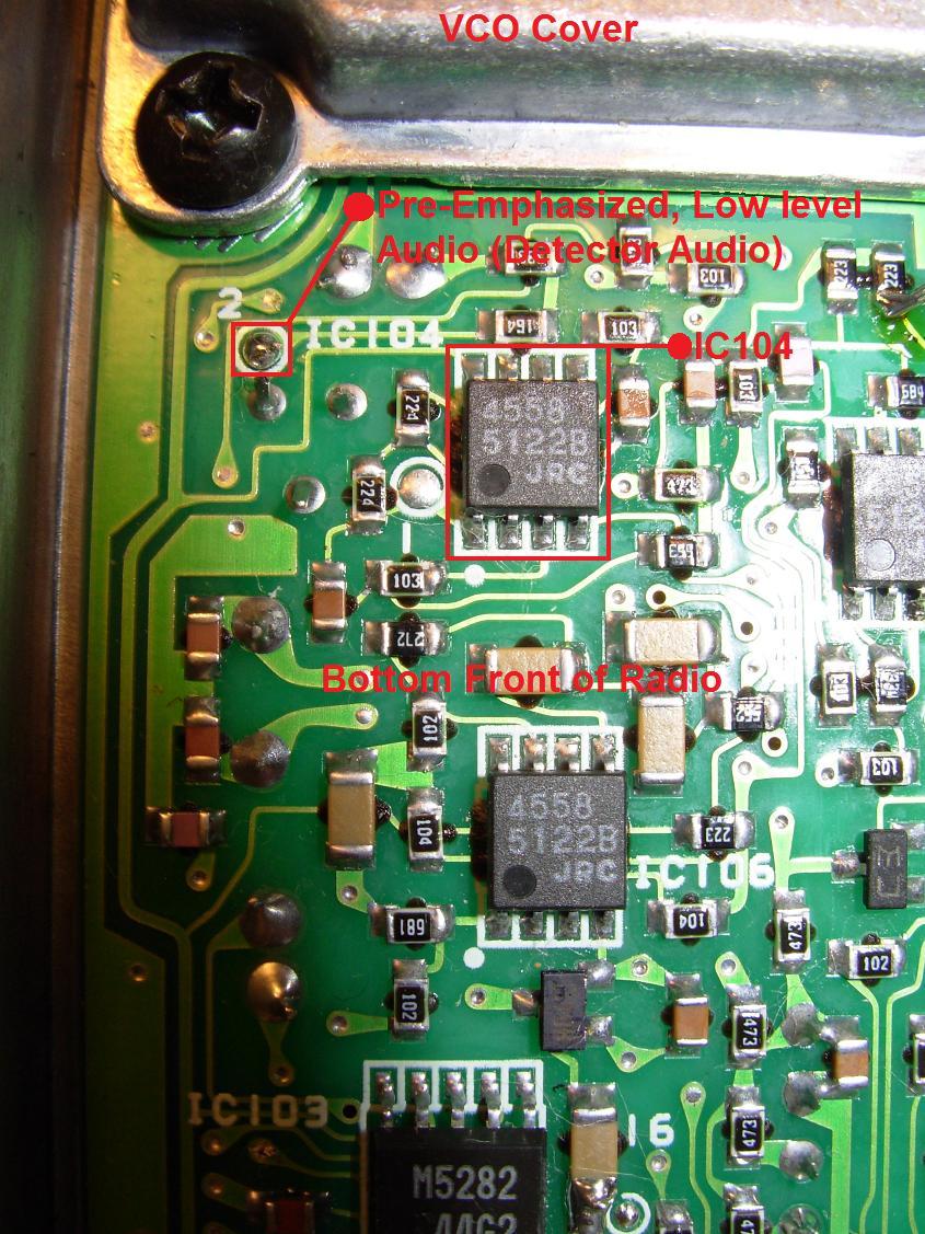
The pick off point if you would like to use Pre-Emphasized, detector audio. Pick off point for this is on a small pad on the bottom of the TK-931, near IC104.
The receivers original ceramic bandpass filters will need to be removed and ones that will pass 902MHz or thereabouts, installed in their place. The filters listed in the TK-931 Filter Changeout section of this website for the normal conversion process will work, as well as ones centered at 902.5MHz, which also exist. The radios ceramic bandpass filters can also be removed and jumpered. My personal opinion of that method is what one might call the “Mickey Mouse Method” as I do not like the idea of doing this; however, with a good duplexer and bandpass filter this is acceptable.
Programming a receive frequency on 902.xxxMHz can be done by hex editing the saved *.F90/*.B90 file and using the KPG-5D software OR you can use Kenwood Burn to do this BUT make sure you leave the repeater offset set to -39MHz, if you change the offset to -25MHz then it will not work!
To program the TK-931 for a 902.xxxMHz receive frequency using the Hex edit method and KPG-5D, create a new data file and ensure you set the radio with transmit inhibit enabled, and any other settings you desire, save the file. Using the Hex editor of your choice, in the saved *.F90/*.B90 file on line 230, column one and two is where you want to add your receive frequency. Then save the hex edited file and write it to your radio using KPG-5D. For example: your repeater receiver frequency is 902.100MHz on line 230 your first column (starting from the left side) should read B8 and second column should read 8D. The chart below shows all 902.xxxMHz repeater receiver frequencies and their corresponding hexadecimal values.
| Frequency | Hex | Frequency | Hex |
| 902.0125 | B1 8D | 902.2625 | C5 8D |
| 902.0250 | B2 8D | 902.2750 | C6 8D |
| 902.0375 | B3 8D | 902.2875 | C7 8D |
| 902.0500 | B4 8D | 902.3000 | C8 8D |
| 902.0625 | B5 8D | 902.3125 | C9 8D |
| 902.0750 | B6 8D | 902.3250 | CA 8D |
| 902.0875 | B7 8D | 902.3375 | CB 8D |
| 902.1000 | B8 8D | 902.3500 | CC 8D |
| 902.1125 | B9 8D | 902.3625 | CD 8D |
| 902.1250 | BA 8D | 902.3750 | CE 8D |
| 902.1375 | BB 8D | 902.3875 | CF 8D |
| 902.1500 | BC 8D | 902.4000 | D0 8D |
| 902.1625 | BD 8D | 902.4125 | D1 8D |
| 902.1750 | BE 8D | 902.4250 | D2 8D |
| 902.1875 | BF 8D | 902.4375 | D3 8D |
| 902.2000 | C0 8D | 902.4500 | D4 8D |
| 902.2125 | C1 8D | 902.4625 | D5 8D |
| 902.2250 | C2 8D | 902.4750 | D6 8D |
| 902.2375 | C3 8D | 902.4875 | D7 8D |
| 902.2500 | C4 8D | 902.5000 | D8 8D |
| Frequency | Hex | Frequency | Hex |
| 902.5125 | D9 8D | 902.7625 | ED 8D |
| 902.5250 | DA 8D | 902.7750 | EE 8D |
| 902.5375 | DB 8D | 902.7875 | EF 8D |
| 902.5500 | DC 8D | 902.8000 | F0 8D |
| 902.5625 | DD 8D | 902.8125 | F1 8D |
| 902.5750 | DE 8D | 902.8250 | F2 8D |
| 902.5875 | DF 8D | 902.8375 | F3 8D |
| 902.6000 | E0 8D | 902.8500 | F4 8D |
| 902.6125 | E1 8D | 902.8625 | F5 8D |
| 902.6250 | E2 8D | 902.8750 | F6 8D |
| 902.6375 | E3 8D | 902.8875 | F7 8D |
| 902.6500 | E4 8D | 902.9000 | F8 8D |
| 902.6625 | E5 8D | 902.9125 | F9 8D |
| 902.6750 | E6 8D | 902.9250 | FA 8D |
| 902.6875 | E7 8D | 902.9375 | FB 8D |
| 902.7000 | E8 8D | 902.9500 | FC 8D |
| 902.7125 | E9 8D | 902.9625 | FD 8D |
| 902.7250 | EA 8D | 902.9750 | FE 8D |
| 902.7375 | EB 8D | 902.9875 | FF 8D |
| 902.7500 | EC 8D |
The TK-931 as a Repeater Exciter
The TK-931’s can be used as a repeater exciter for driving a Milcom/Crescend/Powerwave, DB Products, or Motorola cellular amplifiers. For example a 15 watt TK-931 or TK-931(D) can be adjusted so that the power output is as low as 7 watts output for driving a STF2520A Motorola Cellular amplifier to 115+watts out.
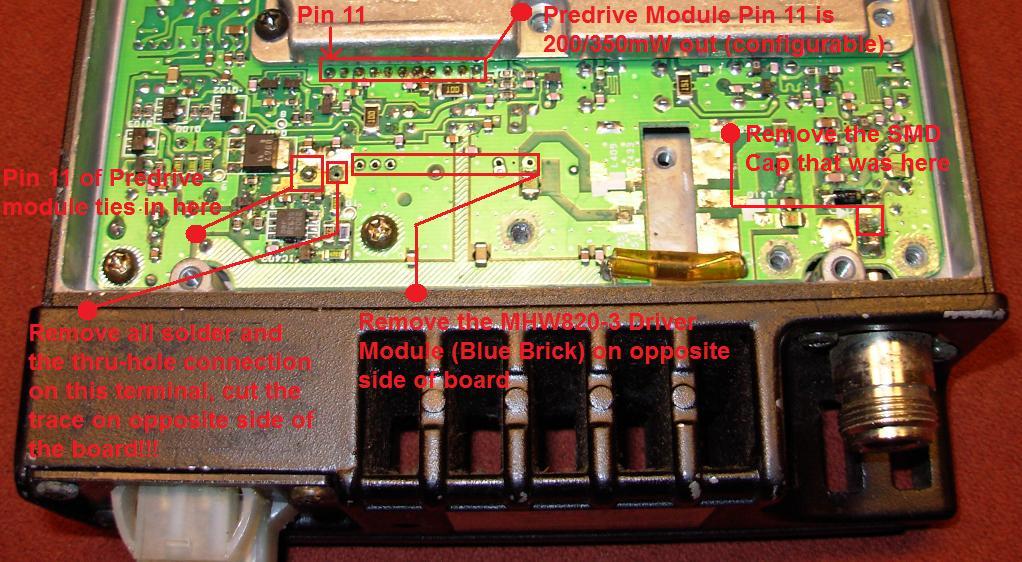
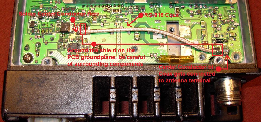
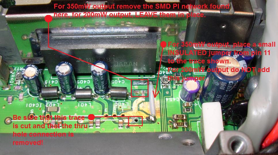
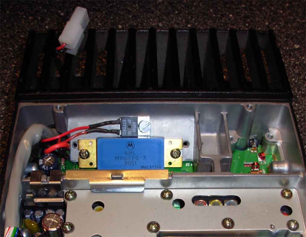
Using the pre-drive module (M57781), the TK-931 or TK-931HD can be arranged to get 200mW out or 350mW out for driving a Milcom or DB Products amplifier (depending on the amplifier drive power required padding might be needed to drop the power out to even less). The modification to create a low power exciter is the same for both the 15W and 30W TK-931's. In either the 15 or 30W TK-931's you will need to remove the MHW820-3 Hybrid Module (Blue Brick). As an added note, on the 30W TK-931HD you DO NOT need to remove the Motorola MRF847 Final PA module- the pictures below show it removed- this was because it was reused in another radio that had a dead PA. To get the RF from the low power pre-drive module M57781 you can then connect a small length of RG-316 coax to the output of the pre-driver module (M57781) which is Pin 11 and jumper it to the antenna terminal directly.
For 200mW of RF output leave the SMD resistors R406, R407, R408, and R409 in place on the output of the pre-drive module, this is a PI attenuator network.
If you need 350mW out, REMOVE the SMD resistors R406, R407, R408, and R409 and add a small INSULATED jumper (the center conductor with the shield removed from RG-316 coax works well) from Pin 11 on the output of the pre-drive module to the terminal shown on the pictures below.
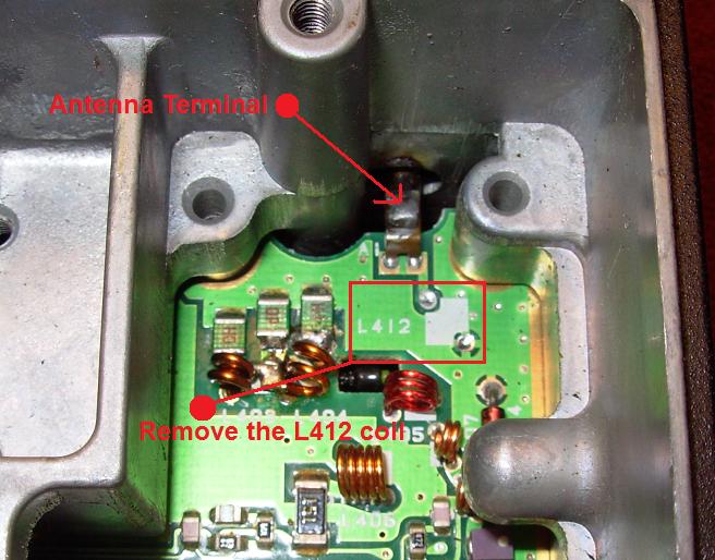
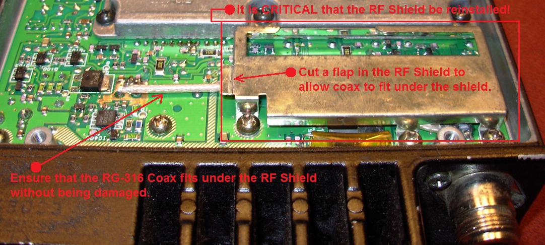
For BOTH 200mW or 350mW RF Output you will need to remove the SMD Cap C441 near the antenna terminal, the L412 Coil on the top side of the board near the antenna terminal, the MHW820-3 Hybrid Module (Blue Brick), and finally you will need to remove the thru-hole terminal and cut the trace that connects to pin 2 (the bias pin) of the MHW820-3 Hybrid Module as shown below. The MOST important step is to reinstall the RF shield on the bottom of the radio and ensure that you cut an opening in the shield so that the coax can pass under the shield without being pinched. This setup will give you a very reliable low power exciter on 900MHz, with no cooling fan required!
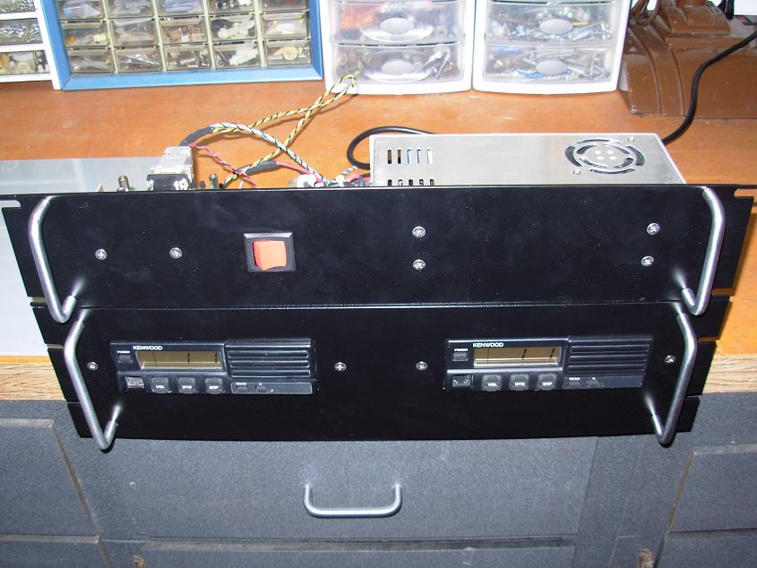
Shown below is a 15 watt TK-931 used as a repeater exciter. The main board is a 15 Watt TK-931 that has been removed from the short heatsink chassis and remounted in a 30 watt TK-930HD (800MHz) chassis- taking advantage of the larger heatsink. The chassis was salvaged from a dead TK-930HD that was also used for parts. The HD 30 Watt chassis are the exact same as the low power short heatsink chassis, so the swap is easy! Please see the "TK-931L" section of this website for the TK-931 long heatsink how-to! With the radio output power set to 7 watts in this configuration you can run this radio at continuous duty cycle to drive a Motorola STF2520A cellular amplifier to 120 watts out. It should be noted that you do not want to run the radio below ~7 Watts because the switching transistor, Q401, will fail due to heat caused by turning back the power below 7 Watts. This radio used as an exciter at 7 to 10 Watts runs cool in continuous duty operation and as added protection (if need be) a thermal switch was mounted just above the PA module to power on a cooling fan (not shown) if unit reaches 140deg F.

TK-931 Repeaters in Service
W7UVH Kalama, WA Repeater, 927.2750MHz QT 114.8Hz
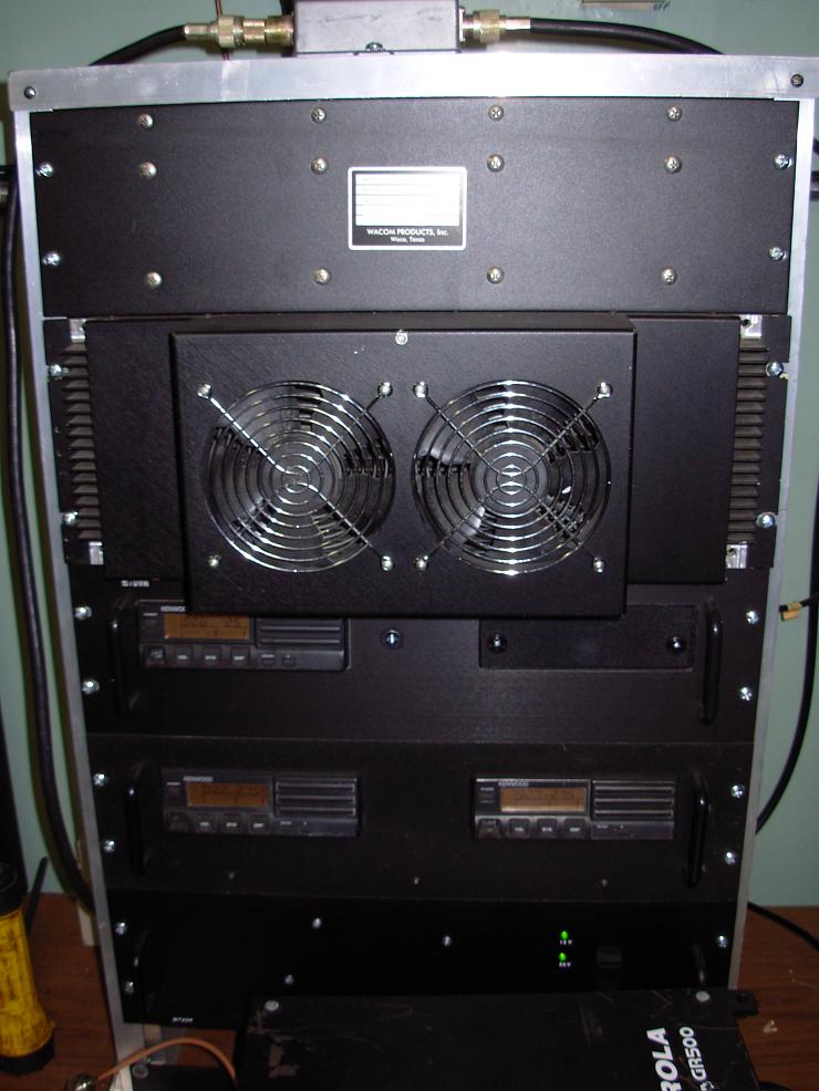
N8WAC Ohio Group Repeater, 927.0250MHz QT 131.8Hz
Repeater has since been replaced.
KD6VPH Bush Mt., WA Repeater 927.7500MHz Repeater, QT 114.8Hz
Repeater has since been replaced.