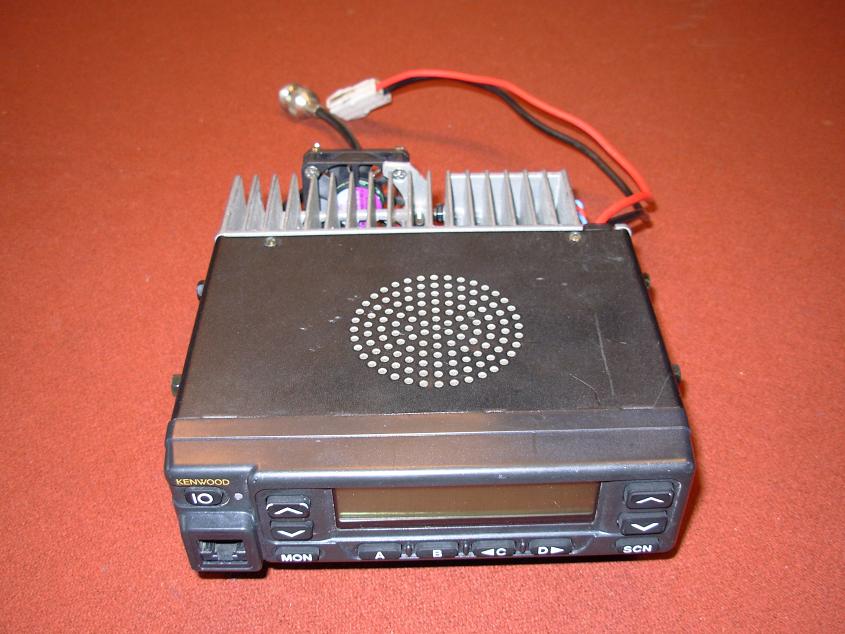
The 30 Watt TK-981H
First and foremost the TK-981H never existed; it’s my name for the 30+ Watt TK-981 that you yourself can build. The idea for a TK-981 that did at least 25 watts out started a few years back over lunch with Gene, W7UVH, the idea got put on the back burner but just recently the thought re-emerged when I acquired a water damaged TK-880H (40 Watt, UHF) radio from that ever popular auction site for around $25. I had plans to salvage the radio but the display was too damaged to bother, long story short , the extra long heat sink from the 40 Watt TK-880H looked like it could be used for a TK-981 high power model.
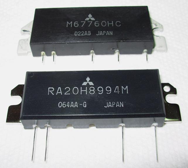
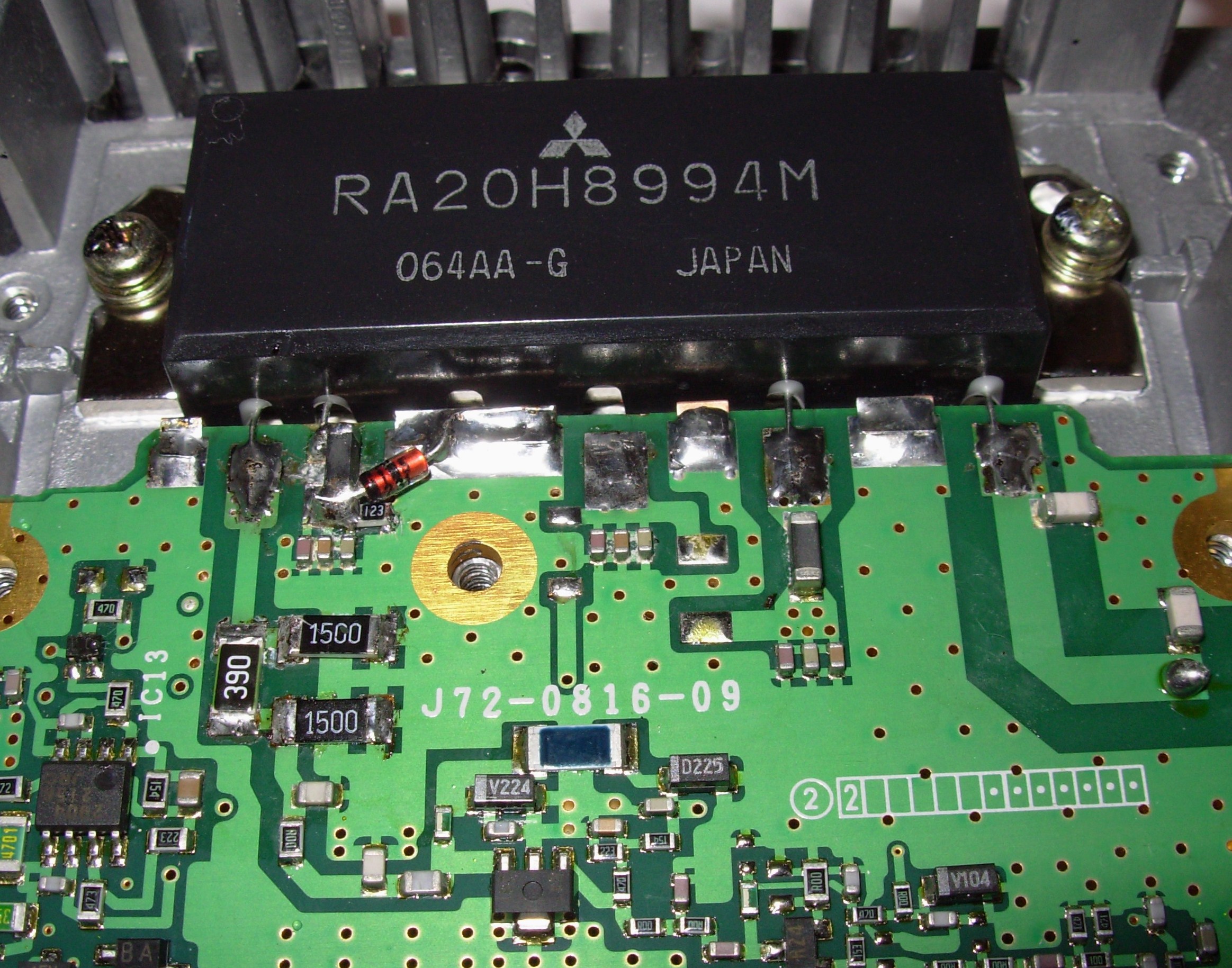
After looking through the list of hybrid modules listed on the RF Parts website I found the Mitsubishi RA20H8994M, which has an absolute maximum power out of 40 Watts. The original PA in the TK-981 Version 1 and Version 2 up to serial number 60600000 is the Mitsubishi 67760HC which has an absolute maximum power out of 25 watts- not a good idea to try running the radio anywhere near this.
After doing a little comparison of the 2 PA modules the ideas started flowing and after a few days of tinkering out came the TK-981H. So in looking at the Version 2 TK-981 with a serial number of 60600001 or higher it should be noted that they use the newer RA20H8994M power module- and the great thing about them is stock they will do 30 watts out!
The only caveat to this high power radio is this; you MUST either use a "H" chassis out of a TK-780H, TK-880H, TK-760HG, TK-860HG, TK-762HG, or TK-862HG (you do not need a fan if you go this route) OR if you use the original chassis run a small 40mm cooling fan on the heat sink of the radio. Running a fan is not a big deal because if you take a look at most of the new amateur mobile radios out there most of them come with a cooling fan.
There are 2 routes to go if you are going to build a TK-981H:
- Route 1: You can modify your existing TK-981 Version 1 or 2- this is the cheapest route as it will cost you around $70 for the RF module and the extra parts needed to modify the radio.
- Route 2: You can try your hardest to scrounge up a Version 2 TK-981 with a serial number of 60600001 or higher- add a 40mm fan and your good to go! As an alternative to using a fan you can mount the main board in a long heatsink chassis (from a TK-780H, TK-880H, TK-760HG, TK-860HG, TK-762HG, or TK-862HG) and run without a fan at 30W. Keep in mind the max rating on the PA module is 40 Watts so running it at 30 Watts output is quite safe.
Before getting started please reference the PDF Datasheets for the Mitsubishi Power Modules listed above.
Mitsubishi 67760HC Original TK-981 PA Module (5 Pin/20W Module)
Mitsubishi RA20H8994M Higher Power PA Module (4 pin/Starting Serial 60600001)
Route 1: Use Your Existing TK-981 Radio for Conversion to 30 Watts Output.
You will need the following Tools:
- 40-50 Watt Pencil Tip Soldering Iron with Solder Wick
- Hot Air Rework station is Optional- Makes the job easier!
- Bird/Telewave Wattmeter- This is NOT optional- you will need one!
- 900MHz 50W Slug if using a Bird Wattmeter
- 50 Watt Dummy Load-This is NOT optional- you will need one!
- Digital Voltmeter- This is NOT optional- you will need one!
- Micro Phillips Head Screwdriver
- Normal Phillips Head Screwdriver
- X-ACTO Knife
- Liquid Solder Flux
- Heat Sink Thermal Compound (Zinc Oxide)- This is NOT optional
You will need the following Parts:
- One Mitsubishi RA20H8994M- can be purchased from RF Parts Company, you can find the link to their website via the "Links" section of this website.
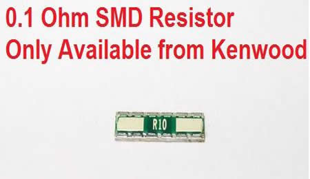
- One 0.10 Ohm SMD Resistor Kenwood Part Number R92-2680-05, this can be purchased from East Coast Transistor or Pacific Coast Parts.
- One 5.1 Volt Zener Diode NTE Part # 5010A (1/2 Watt, Axial Lead)
- One 1/8 Watt 15K Ohm Resistor Axial Lead OR SMD
- Two 150-Ohm 1/2watt SMD resistors
- One 39-Ohm 1/2watt SMD resistor
- One 1.8K Ohm SMD resistor
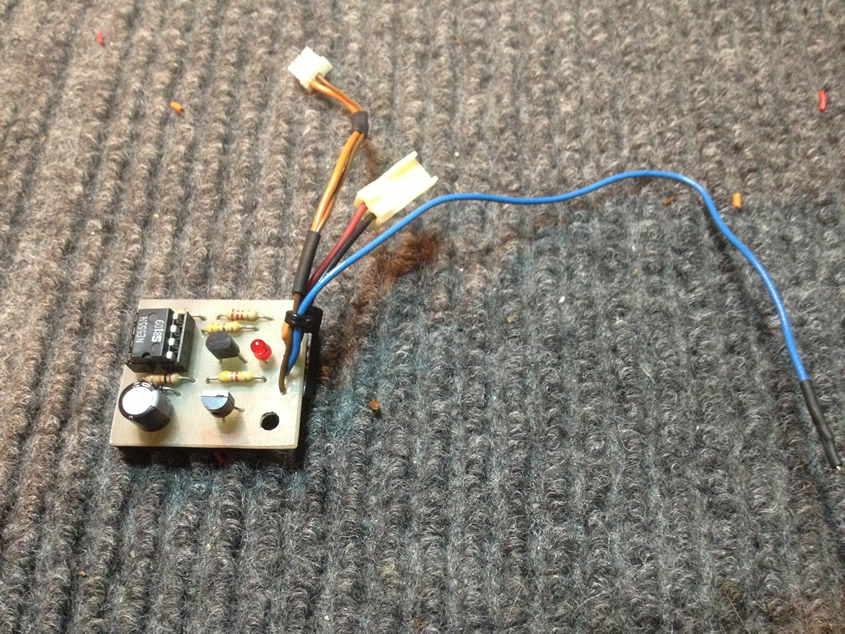
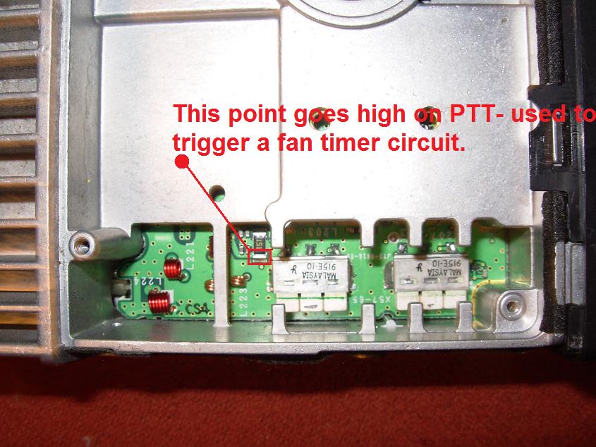
- Either a dead TK-880H, TK-780H, TK-760HG, TK-860HG, TK-762HG, or TK-862HG Chassis OR a 40mm cooling fan for cooling the radio during long transmissions and a timer circuit or thermal switch to control when the fan powers on or off. I use a 2 minute timer circuit which uses a simple 555 timer triggered on by the PTT.
BEFORE WE START:
Make sure that you understand that this modification is NOT for the beginner or even moderate beginner, it requires good knowledge of proper soldering techniques, soldering of Surface Mount Devices (SMD's), and the proper test equipment. SMD's are delicate and not terribly easy to work with. Know YOUR limitations and don't try to do this modification if it is beyond your current skill level. YOU HAVE BEEN WARNED! You should also be aware that modifying this radio will nullify the radios type-acceptance for use in commercial service.
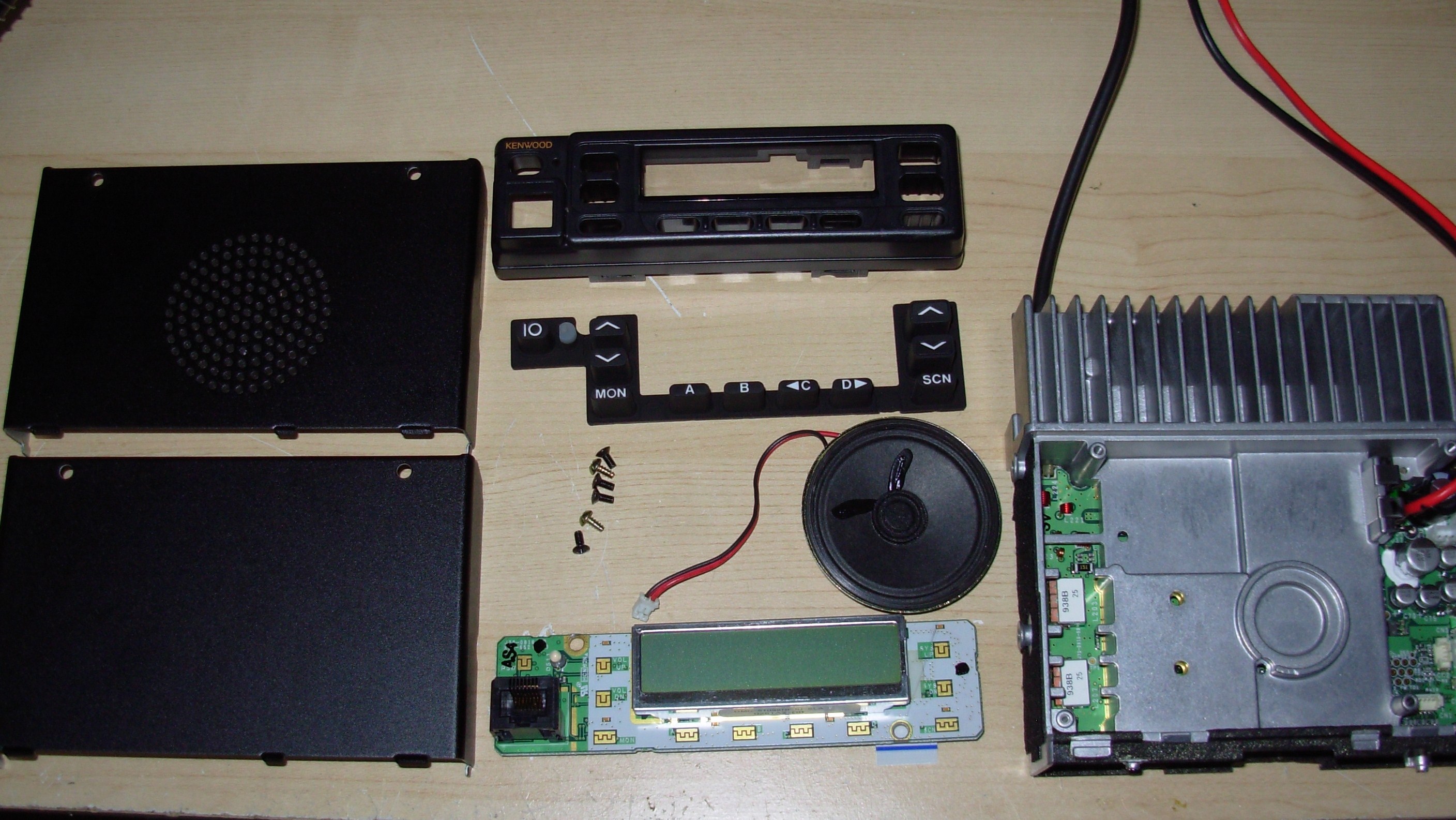
- Ensure that your radio is working properly and functioning correctly, there is no point in modifying a radio that is damaged. Remove the top and bottom covers of the radio, the speaker, the front panel and display. Removal of the display will require you unplug the ribbon cable in the front of the radio- be very carefull in doing this!
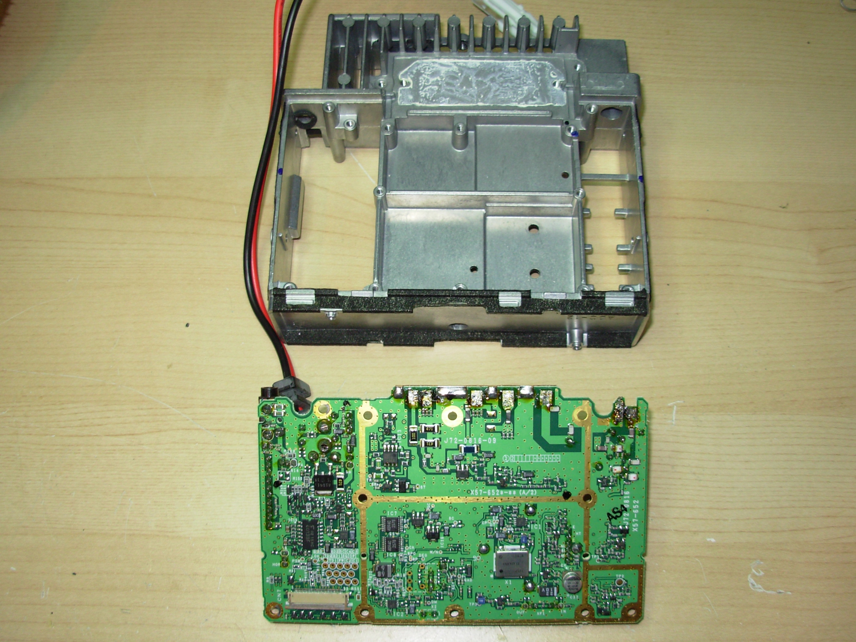
- The next step in the process is to remove the clip that holds the audio PA securely to the chassis, and the clip that the 7808 Voltage regulator and the APC drive transistor to the 981 chassis. Flip the radio over and remove the large RF shield that covers the PA module. At this point we also want to remove the 2 screws holding the coax pigtail in place and de-solder the the coax and remove it, be carefull in doing this, as too much heat can remove the trace from the main board.
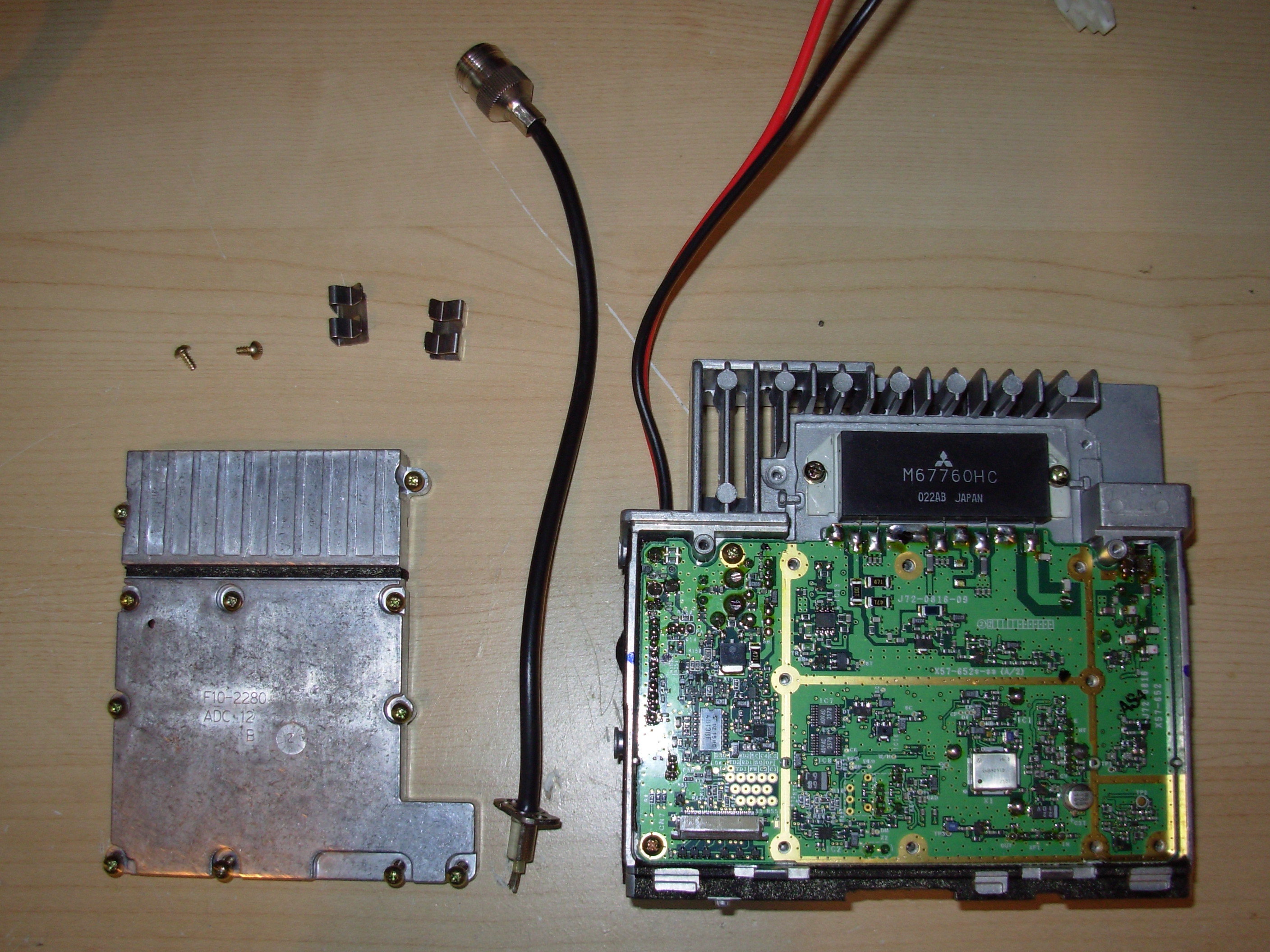
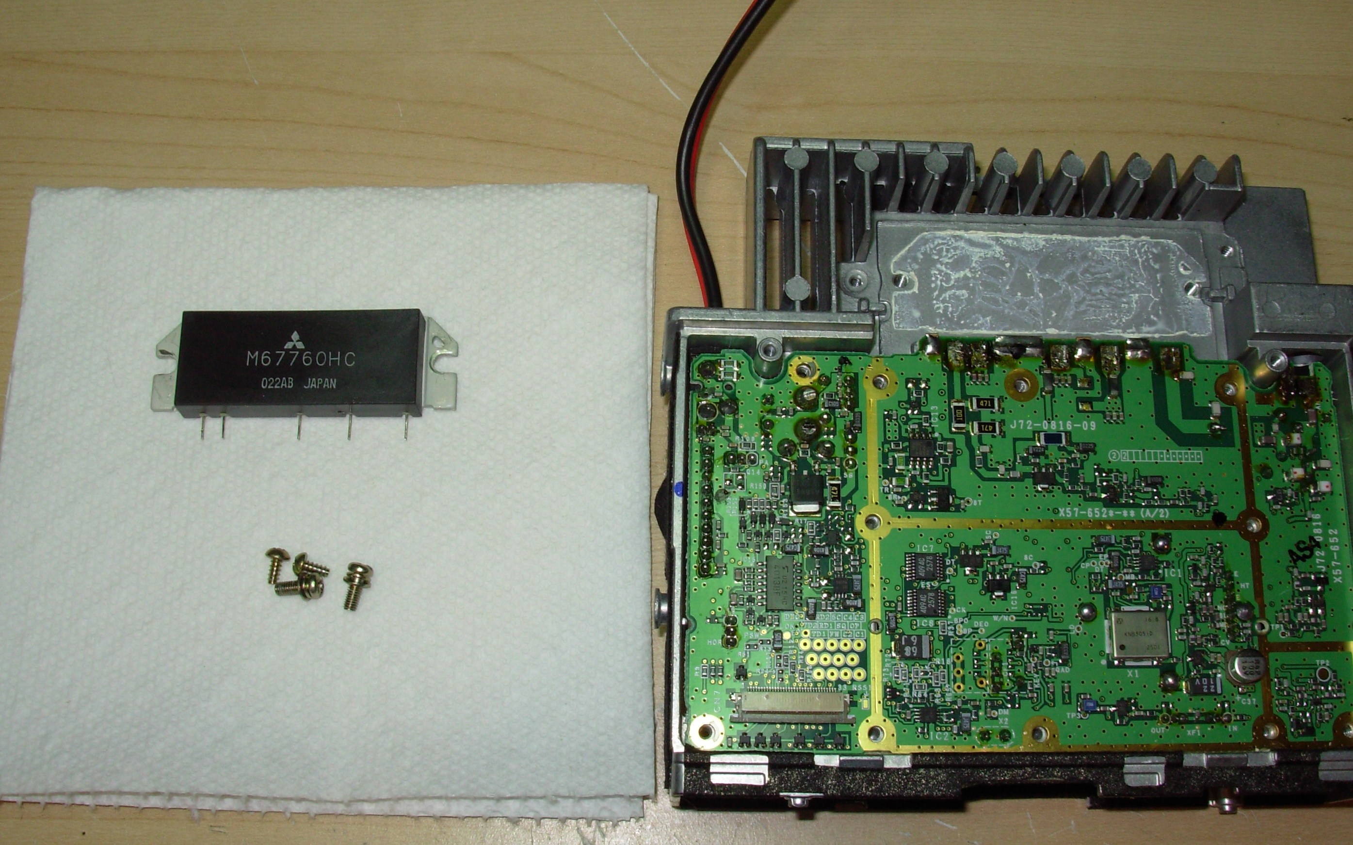
- We now want to remove the existing low power PA from the main RF board. I have found that a combination of a solder bulb sucker and solder wick are best in removing the large globs of solder from the PA pins. It would be a good idea to save the old PA for a spare or to sell it to try an recoup some of the money spent on the higher power PA. Also at this step you will need to remove all the securing screws that exist on the bottom side of the board to facilitate removal of the entire assembly.
- We can now remove the entire board from the main chassis. When doing this it is best if you leave bottom of the radio facing you and push gently up on the front of the board while pulling the board out towards you through the front of the radio- be careful of the black felt ring that surrounds the external speaker jack.
- Now we must remove the group of resistors that act as padding to attenuate the output of Q204 by 3dB. This group of resistors make up a PI Attenuator Network comprised of R247, R248, and R249. There are a couple variances that Kenwood used in this network of resistors, I have shown pictures of this below.
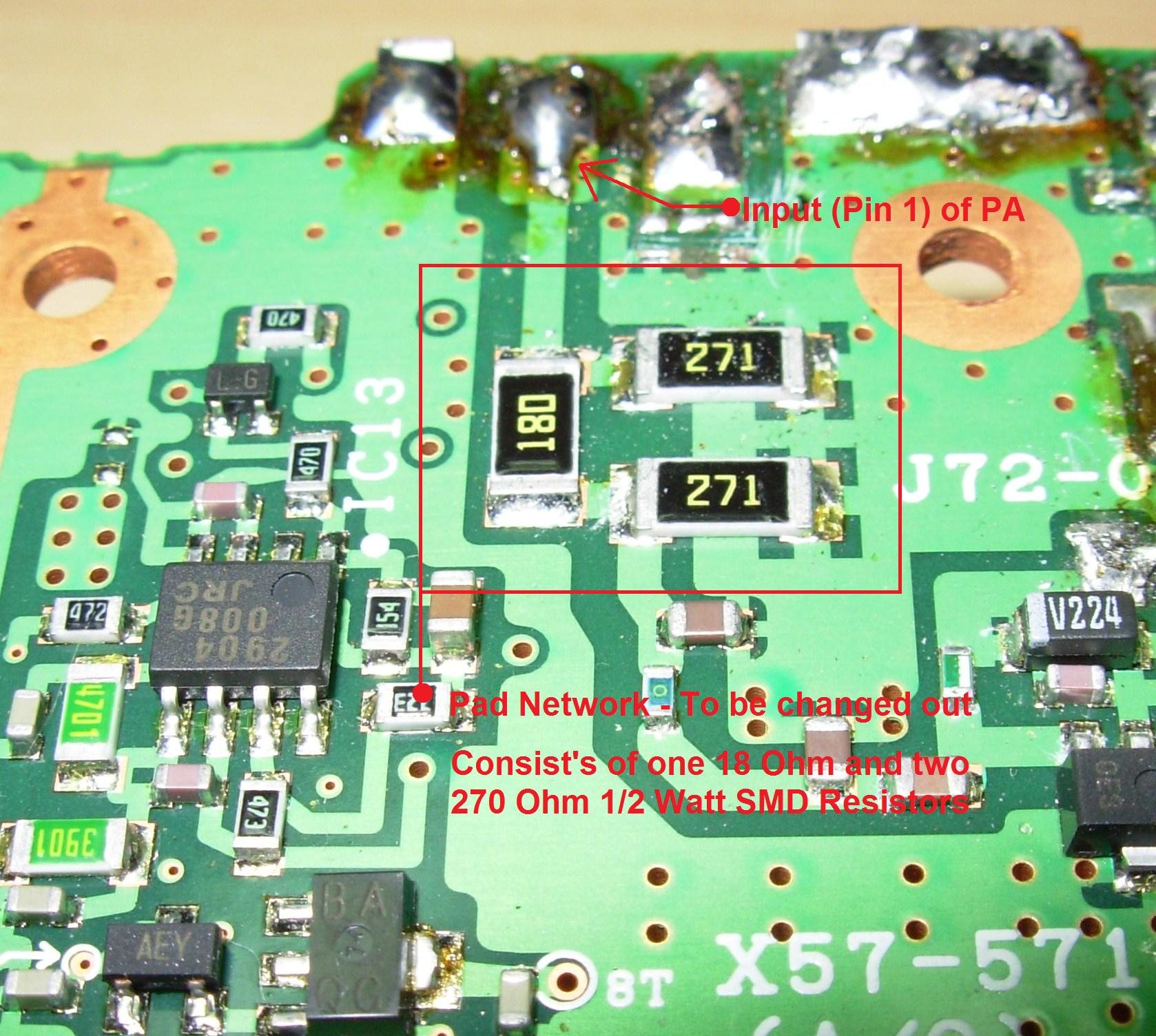
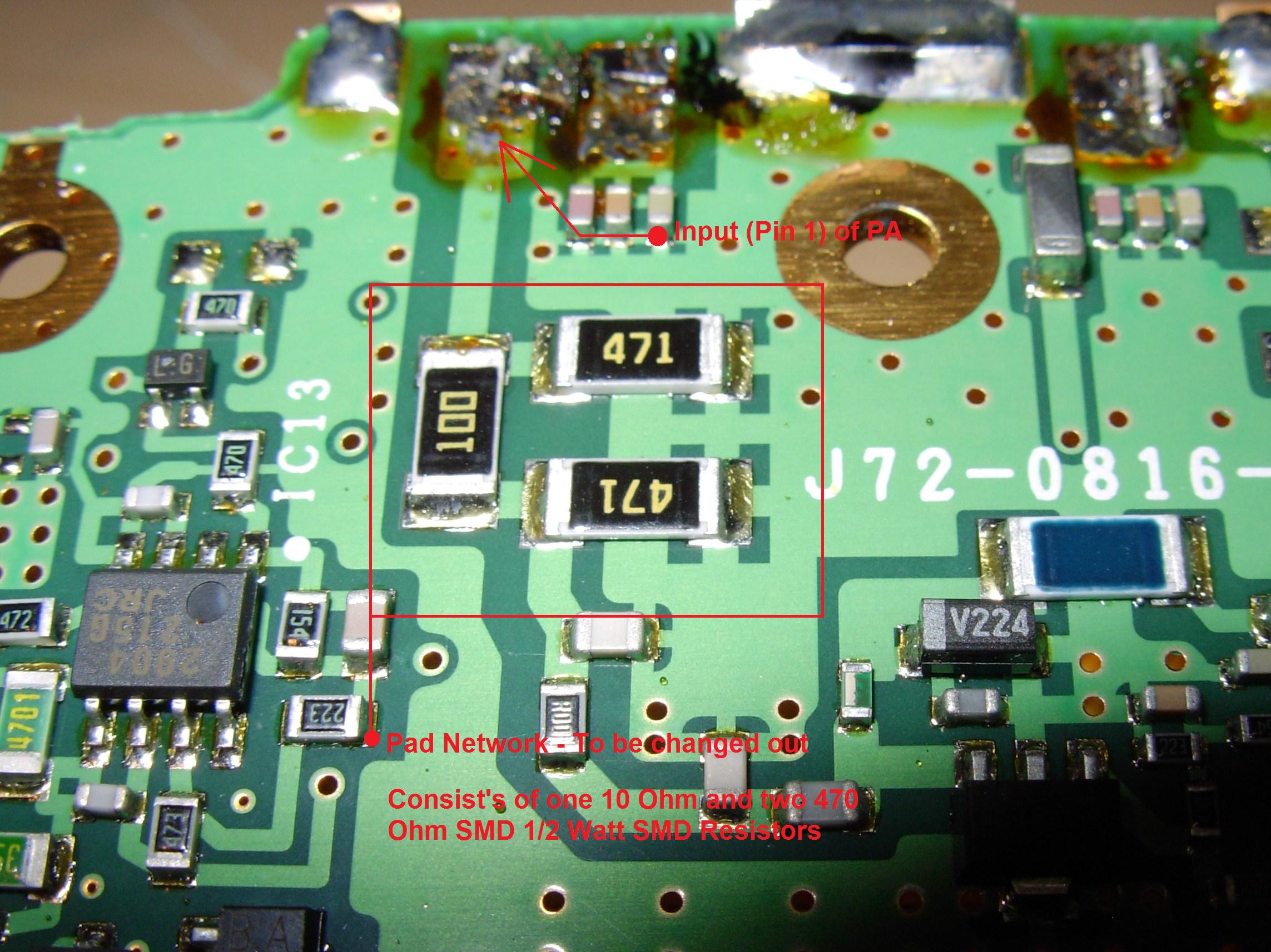
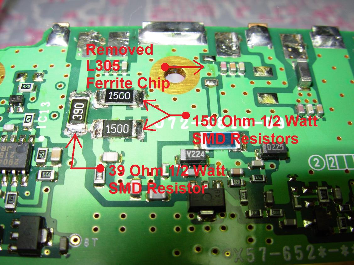
- The newer Mitsubishi RA20H8994M has a maxiumum input of 100mW which is far less the the older Mitsubishi 67760HC. To remedy the difference in power input levels to each module we are going to add 3dB more of attenuation for a total of 6dB. This will prevent us from running the risk of overdriving the newer Mitsubishi RA20H8994M. Carefully using either solder wick and your 40-50W iron or your hot air rework station (preferred) remove these 3 resistors. We will also be removing L305 which is a SMD Ferrite Chip. You will need to remove this chip carefully as we will be reusing it on pin 2- remove and place it in a safe spot.
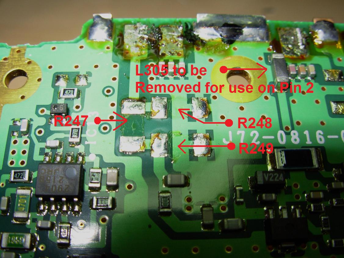
- We can now install the new 6dB PI Attenuator Resistor Network. R248 and R249 are going to be 150 Ohm 1/2 Watt SMD resistors and R247 is going to be a 39 Ohm 1/2 Watt Resistor. Also notice that by this step we have removed the L305 Ferrite SMD chip. We will reinstall L305 at a later step.
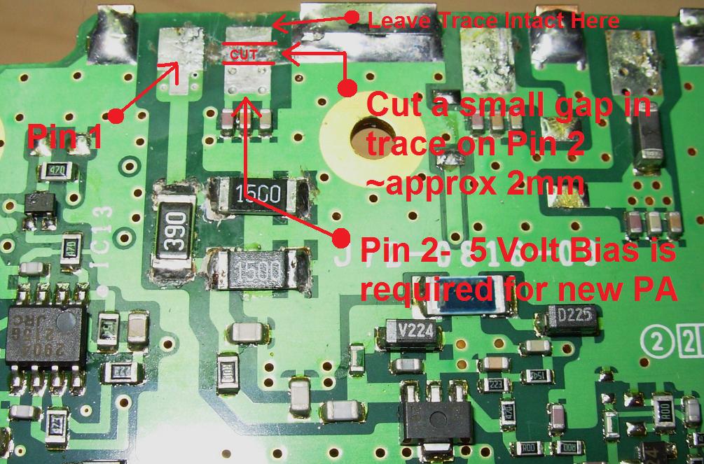
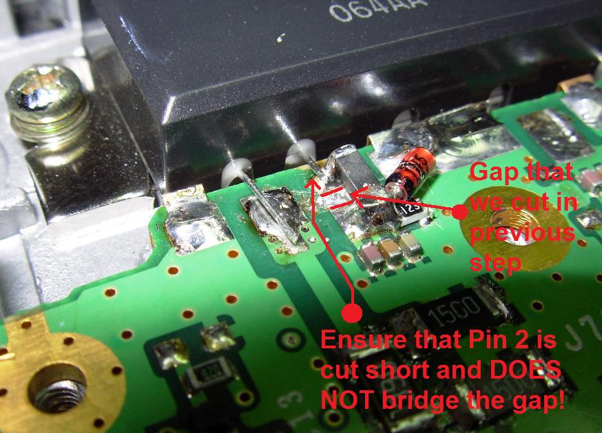
- Next we are going to VERY carefully using our X-Acto knife cut a gap of approximately 2-3mm on Pin 2 of the board, leaving material to solder to on the PA side of the board. We are leaving material behind to be able to solder L305 to bridge the gap.
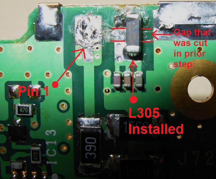
- We can now install L305, our Ferrite SMD Chip on pin 2. The chip will be placed so that it bridges the traces that we just cut. Position L305 so that it is positioned towards the right side of the traces (see photo), this will allow us to install the PA pin 2 on the left side of the trace.
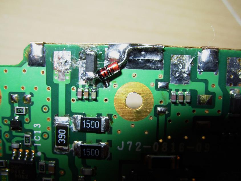
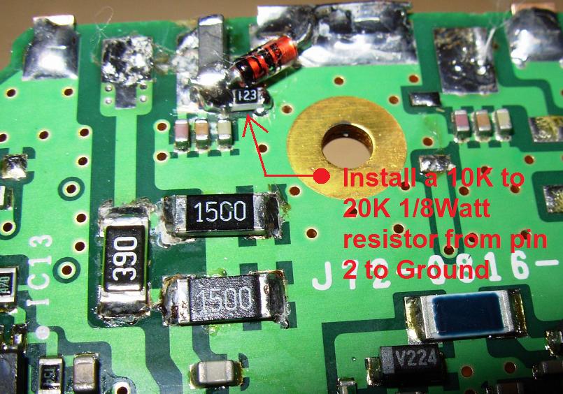
- We can now install our NTE5010A 1/2 Watt 5.1V Zener Diode. This diode will regulate the previous +8Vdc bias down to +5Vdc that is switched on during PTT. Will install the diode with the Cathode towards pin 2. We are also going to install a 15K Ohm resistor from Ground to Pin 2 so make sure that in this step you leave yourself enough room for a small SMD resistor, you can see in the picture provided the green screen mask has been scraped away just below the body of the diode.
- We can now install the 15K Ohm Resistor that we removed some of the board coating away from in the prior step. I am using a 12K Ohm SMD resistor, you can use any value between 10K to 20K and you don't need to use an SMD resistor, axial lead would work fine as well it need be only 1/8 watt. The white fluff that you can see in the picture is left behind from a Q-tip that was soaked with Flux remover to remove the flux left behind from removal of the PA module.
- Now we can modify the Automatic Power Control Circuit and our Zener Voltage regulating resistor that connects to pin 2 on the other side of the board. Flip the board over and locate the 0.1 Ohm sensing resistor and +8Vdc trace that passes under C257 a 47uF 25V Electrolytic SMD Capacitor.
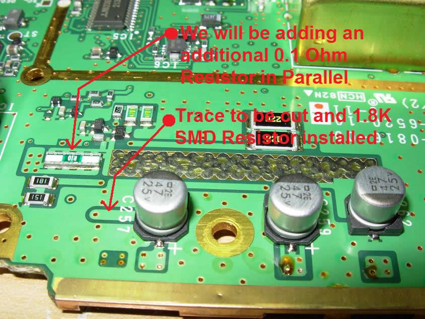
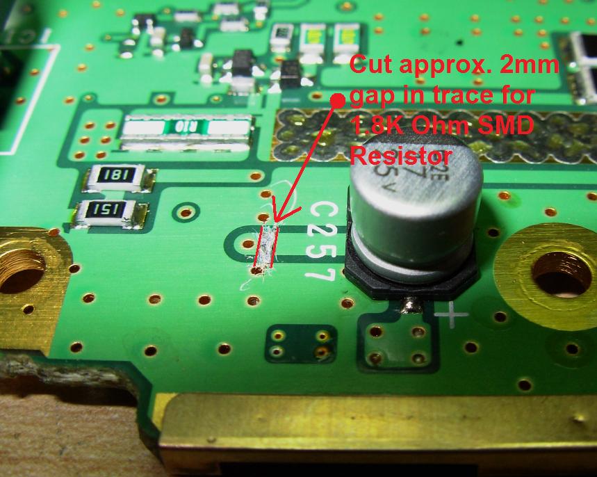
- Now cut a gap in the trace going under C257 a 47uF 25V Electrolytic SMD Capacitor of approximatly 2mm so that we can mount a 1.8K Ohm SMD resistor across it. You will also need to scrape away some of the green silk screen off the board so it can be soldered to.
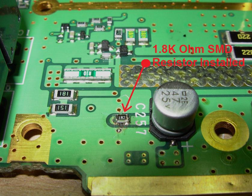
- Now we can attach the 1.8K SMD Resisitor, use a VOM to ensure that the connection is not bridged with solder!
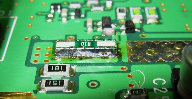
- Now we will install the 0.1 Ohm SMD sensing resistor to the APC circuit. The Resistor is a little unique in that the terminals run along the length of the resistor and not at either end which is why it is important to get this item from either Pacific Coast Parts or East Coast Transistor.
- Installing the 0.1 Ohm SMD power sensing resistor is a little tricky. Its kinda like stacking Oreo cookies. I use a little Liquid Solder Flux to hold the resistor in place and then add a tiny amount of solder to the tip of my soldering iron and run the iron along each side of the resistors all this while gently pushing down on the resistors with an X-ACTO knife.

- The installed resistor should look like one piece when installed, be careful not to apply too much heat.
- At this point we can reinstall the board back in the chassis. We can also install the front display at this point as well. A good idea at this step is to check our work, I did this by attaching a small pigtail of RG-316 with a BNC on the end going to my Bird Wattmeter and terminated to a 50 Ohm dummy load. I use a 500mW element to test the output of the driver module to ensure it is less then 100mW. You will notice that the length of the coax used has a big influence on how much power output is seen on the meter due to the impedance mismatch that is occuring in the circuit because we added coax. The main point is to just ensure that we are getting power out of the unit and at max slider in KPG-49D "Test Mode" we see around 100mW max. One of the most important safety steps (for the radio, not you!) is this: if you are going to test the unit before you mount the PA module ENSURE that you have AT LEAST 4 ground screws installed to the chassis!

- We can now install the PA in the the chassis and make all connections. You will notice the difference in appearance of the old (top) and new (bottom) PA modules.
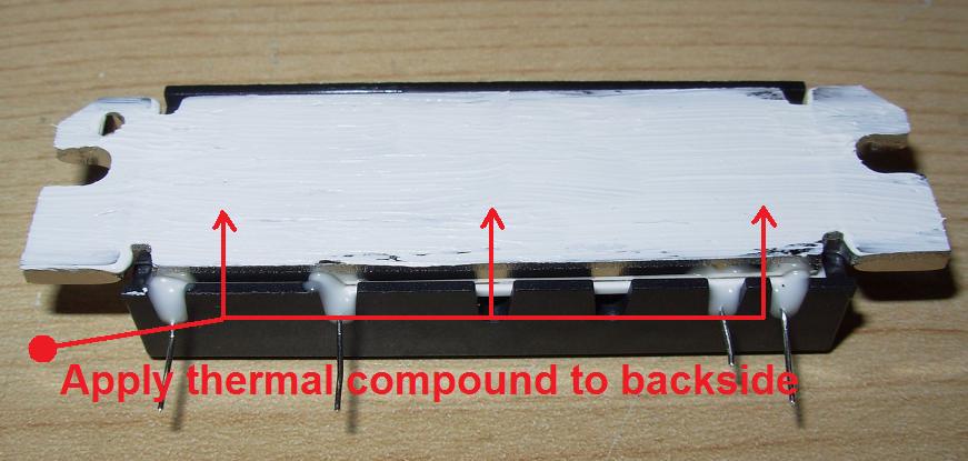
- We need to apply thermal compound (heat sink compound) to the backside of the PA before installing. This will better conduct heat away from the PA to the external heatsink.
- We now secure the PA to the chassis and cut the lead lengths for pins 1 through 4 to the appropriate length. The most critical pin is is pin 2- ensure that this pin is cut short so that it is terminated on one side of L305 and DOES NOT bridge the gap that we created.
- We are just about finished at this step. Solder all leads of the PA to the board, and remove all excess solder flux using solder flux remover or Isopropyl Alcohol of at least 90%. It is important to inspect all areas of our work to ensure that in handling the board nothing was damaged or any solder was splattered in a place its not supposed to be. We can now install the PA RF shield and the RG-58 N-connector Coax Pigtail, as well as the Speaker, Audio Amp/8V regulator retainer clips, and top and bottom covers.
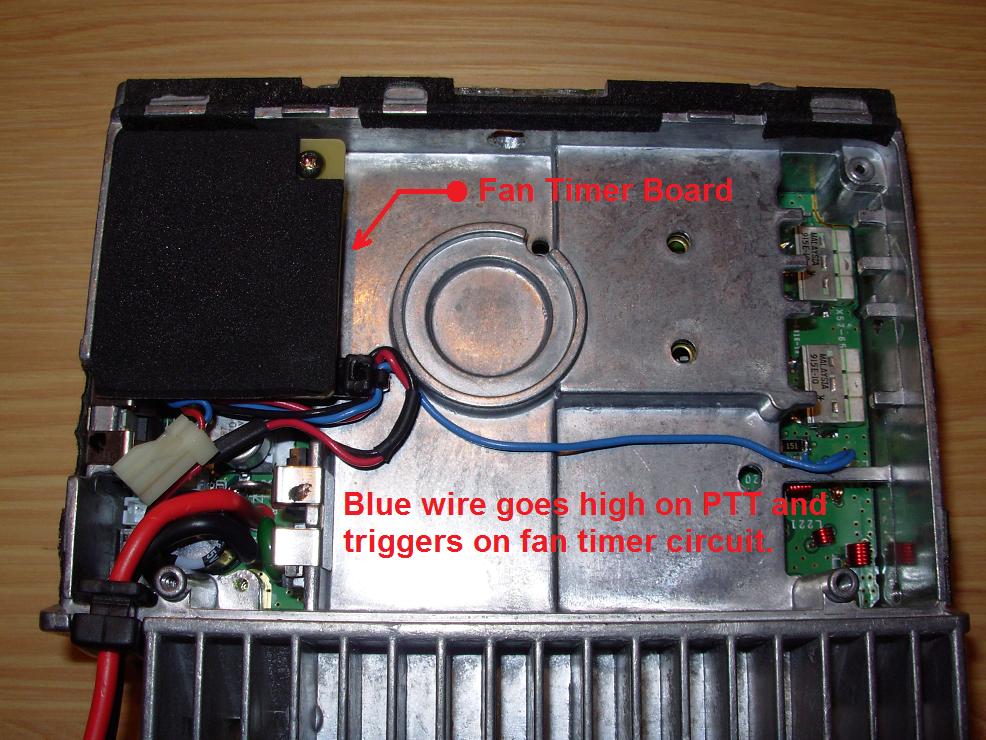
- We now need to add a cooling fan to our radio. For a cooling fan I simply use a 40mm cooling fan, with a Ball Bearing and Brushless motor which is mounted to the rear heatsink. The fan is triggered on when the PTT is pressed and stays on for ~2 minutes. The circuit I used for the fan switches on the fan when triggered high and uses a 555 timer circuit and 2N2222 transistor to switch the NEGATIVE lead of the cooling fan on- this is better then switching the positve lead of the cooling fan if you want to avoid any chance of fan noise/hash. For a very simple and easy to build fan control circuit see the "Downloads" section of this website for N4MW's fan control circuit. If you are using the long heatsink TK-x80H/TK-x62HG chassis then you can get away with not running a cooling fan. If you are using the existing short heatsink (original TK-981 chassis) you CANNOT run this radio at 30 Watts without a cooling fan, you have been warned!

- We can now re-adjust the power out and test our radio. This is probably the most important step and is critical for the proper operation of the radio at 30 watts!!!
In KPG-49D Versions 4.01, 4.02, and 4.20 (Windows based versions) read from the radio and go into "Test Mode". From there adjust the power output on 902 MHz for 30 Watts and then adjust the power output at 927MHz (Talkaround) for ~25 Watts using a high quality Wattmeter such as a Bird or Telewave unit into a 50 Ohm dummy load- I would not recommend running this radio much above 30 Watts as you are pushing the envelope of what the internal components are able to tolerate! You can also readjust and do a full alignment on the radio setting the maximum deviation, QT/DQT Deviation, Modulation Balanced, etc...