TK-931 Troubleshooting Section
“Help! My Radio Will Not Program.”
1. Check the Kenwood Burn program- does the COM port setting in the program match where the KPG-4 Program Cable is actually connected?
2. Is your KPG-4 programming cable faulty/broken?
3. Is the radio in Program Mode? If the alphanumeric display (TK-931 D/HD) does not read “PROGRAM” or on the TK-931 the non-alphanumeric display does not show two hyphens “ - - “, then you are not in programming mode! Switch the radio off then press the “POWER” button while holding the “A” button for 5 seconds then release- the display should now say “PROGRAM” or have two hyphens “ - - “ showing.
4. Are you using a laptop? Some laptop computers do not have enough power at the serial port to be able to program a radio- this is not very common but does occur- try a desktop computer.
5. Does the radio think that the radio microphone is “on hook”? “Hook” is referring to the microphone hook/clip. The radio uses a microphone with a metal backing hook, when this metal backing is grounded, i.e. the microphone is hung up on a grounded metal microphone clip, tone squelch is enabled; if tone decode is programmed, or if scan is enabled, System scan will commence as well.
When the microphone is off hook tone squelch and scan are disabled.
The obvious: at this point if you are trying to program the radio you are using the microphone connector port, but someone who owned the radio previously to you may have programmed the radio and then purposely grounded the hook line in the rear of the radio’s Molex connector or internally so that tone squelch will be enabled all the time- if tone decode is programmed. Please also note that System scan will also function as a result of the hook line being grounded.
We already know that programming the radio uses the microphone port; PTT In (pin 3) and Hook Line (pin 6) to transmit and receive data- if the hook line (pin 6) is grounded data is not going to be transferred. The Hook Line on the front of the radio is directly connected with pin 1 of the 15-pin Molex connector on the rear of the radio. If there is a jumper between pin 1 (Hook) and pin 6 (Ground) on the rear Molex connector of the radio then pull off the Molex connector- restart the programming procedure with the Molex connector disconnected then re-connect the Molex connector when finished programming.
The rear Molex connector serves to allow remote faceplate mounting via the KCT-10A/B and KRK-1 remote mounting kit. When remote mounting the faceplate and microphone there has to be a way to have a remote “hook” connection- pin 1 and 6 on the 15-pin Molex connector serves this purpose.
6. “I checked the rear Molex connector and there is no jumper from pin 1 to pin 6.”
Remove the top cover off the radio- look at harness/connector CN2 which is the large gray wiring harness that goes to the 15-pin rear Molex connector on the rear of the radio. If the green wire normally located in slot 1A (HK) is cut and connected to ground directly or cut and connected to the blue wire normally located in pin 6A (GN) then disconnect them from their modified locations and reconnect them to the original locations. Also Check on the bottom of the radio on the solder side of the board- is there a wire jumper placed from terminal 1A to 6A on the opposite side of CN2?
7. “I have tried everything above and I keep getting “Timeout Errors!”
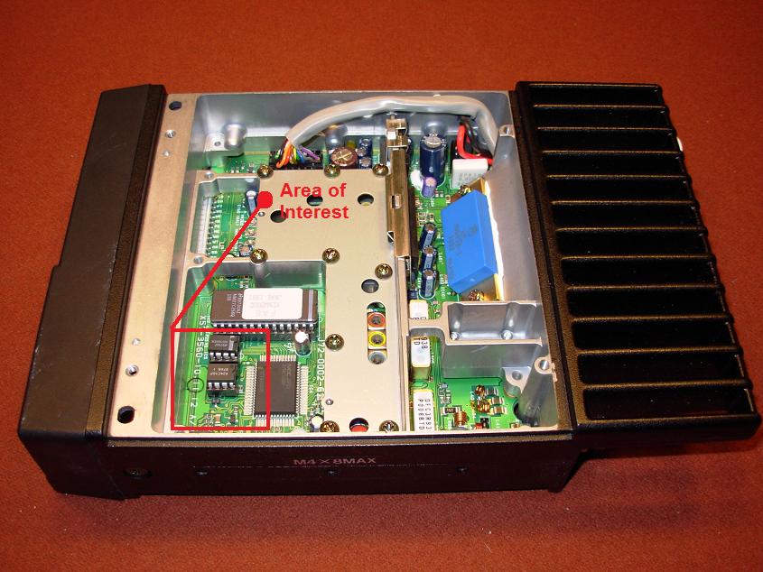
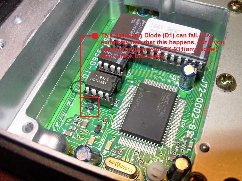
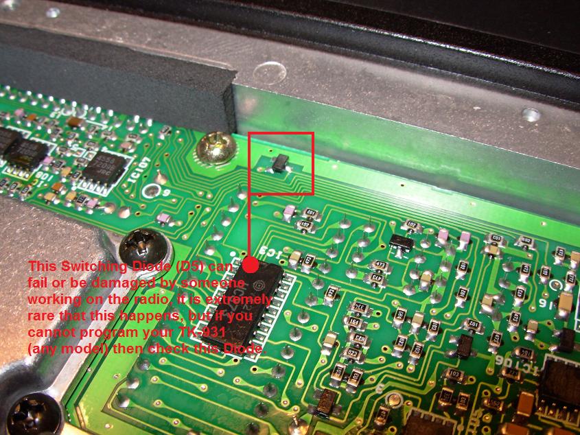
Something internal has probably gone awry! Open the radio and using a service manual trace though the hook circuit and PTT signal in circuits. There are 2 main switching diodes that can fail or be physically damaged (from someone working on the radio); they are D1 and D5. D1 and D5 are 1SS226 (1SS226 Datasheet) switching diodes that are located on the bottom (D5) and top (D1) of the main radio board- regardless of whether you have a TK-931 or TK-931D/HD they are located in the same spot. The pictures below will guide you as to where their exact locations are- be sure to check these diodes. If you do not have a service manual look for the obvious- burnt connections, loose/missing surface mount components, damage to the main board- these are all a long shot without a service manual but at this point why not try?
The location of the D1 switching diode is on the top side of the main board.
The location of the D5 switching diode is on the bottom side of the main board.

8. “I want to give up, it still will not program!”
There is one last ditch effort you can try that will most likely work. I might add that it is EXTREMELY rare that a TK-931 of any version will not program! If you have a TK-931D or TK-931HD remove the top cover off the radio, near the large 28 leg EPROM there are two smaller 8 legged IC’s (93CS66EN and X24C16P) which are the EEPROMS- these store the system/group memories as well as all other user programmable info! Remove both 8 legged IC’s (take note of their orientation!) and place them in a known working programmable radio (same display model, as the displays on the TK-931D or TK-931HD are exactly the same and interchangeable, RF power output does not matter!). Program up the known good radio and then re-insert both the IC’s, in the radio that would not program. It’s that Easy! Please note that you can also do this to a TK-931 as well. If you have a TK-931 that will not program you can use another TK-931 but you will not be able to use a “D” or “HD” radio to do this. In the TK-931 there is only one 8 legged IC (93CS66EN), instead of a second IC (X24C16P) that is found in the TK-931D/HD.
“Help! My TK-931 or TK-931(D)/(HD) powers on but will not power off!"
Kenwood first started production of the TK-931 in the very early 1990's; which is over 20 years ago. These radios, while built to last, have electrolytic capacitors that do have a finite life. The electrolytic capacitors on the main RF board of the TK-931 are rather stout and exhibit few problems over time, however, the aluminum can SMD electrolytic capacitors in the control head of your TK-931 (any model) do need attention. When these aluminum can SMD capacitors age they start to internally break down, when they internally break down the electrolyte (commonly Boric Acid or Sodium Borate) inside them can leak out and cause damage to the surrounding traces and components, as well as cause issues with your radios' power on/off circuit. It is highly recommended that these electrolytic caps be changed out to prevent any possible damage to your radios' control head.
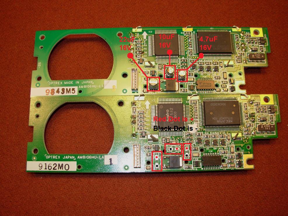
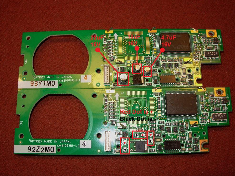
There are 3 SMD electrolytic caps found in the control head of a TK-931 numeric-only or TK-931(D)/(HD) alphanumeric display: 22uF 16V, 10uF 16V, and a 4.7uF 16V. The existing capacitors can be renewed with either thru-hole or SMD electrolytic capacitors and once renewed the control head will be service free for another 20+ years. When you remove the existing caps be VERY careful; do NOT pull on the caps, or put any strain on the traces they are connected to as damage to the existing traces can result. After removal of the caps clean, clean, clean the surrounding areas with isopropyl alcohol of 90% or greater and a Q-tip, don't be frugal with cleaning the area around each capacitor; use plenty of isopropyl alcohol and be very, very careful not to tear any of the traces or surrounding components off the board.
The Digi-Key part numbers to replace the above mentioned Aluminum Electrolytic SMD capacitors are as follows:
4.7uF 25Vdc Digi-Key Part Number: PCE3910CT-ND
10uF 25Vdc Digi-Key Part Number: PCE3894CT-ND
22uF 16Vdc Digi-Key Part Number: PCE4395CT-ND
Shown below is a alphanumeric TK-931(D)/(HD) control head with the aluminum can capacitors intact and removed. Be sure to pay attention to the polarity of each capacitor before removing it.
Shown below is a numeric-only TK-931 control head with the aluminum can capacitors intact and removed. Be sure to pay attention to the polarity of each capacitor before removing it.
“Help! My radio will not power on.”
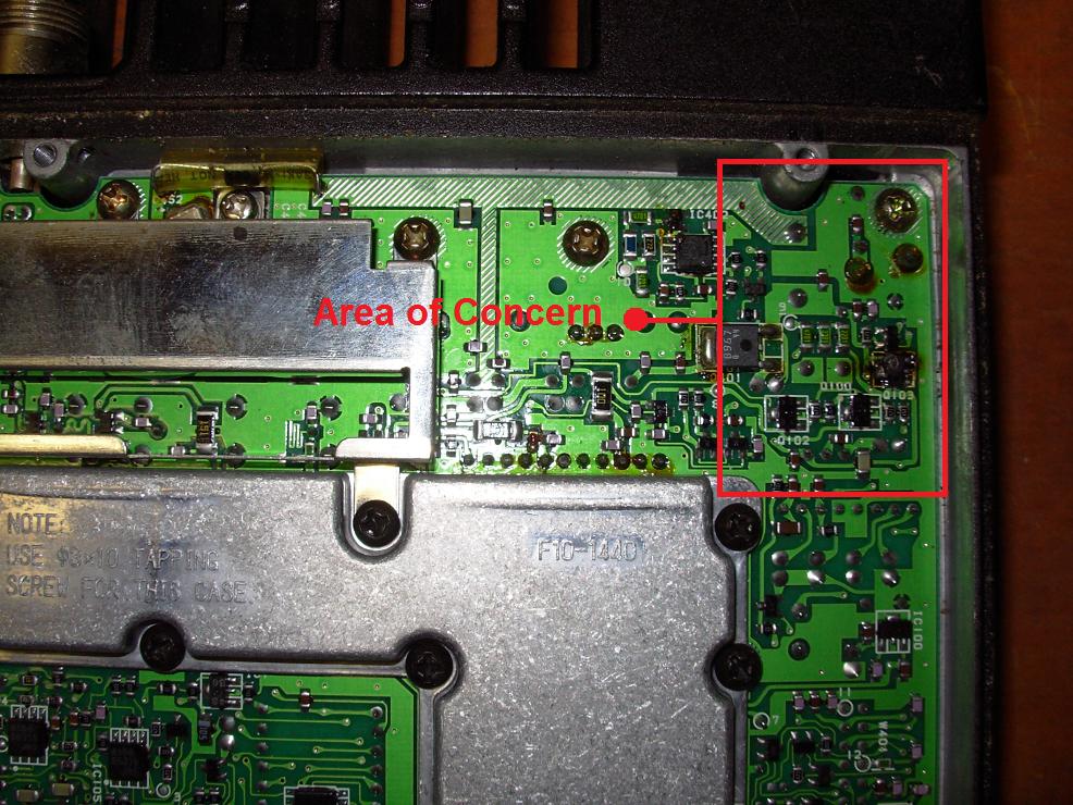
First, there could be a few reasons for your TK-931 (any model) not powering on, such as water damage, tinkering (previous owner), dropping the radio, and coffee; which is most commonly spilled into the front display panel etc... But one thing to check and see is if Q103 is burnt up. Q103 is a switching transistor responsible for switching on the transceiver after the power button is pressed by supplying B+ to the SB line. This transistor can be damaged or destroyed by previous users of the radio- this is most easily accomplished by grounding Pin 7 of the rear 15-Pin Molex connector- i.e. DO NOT EVER GROUND PIN 7 of the rear Molex Connector.
If your radio will not power on and you have checked the obvious then remove the bottom cover of the radio and in the rear of the radio, right corner near the power plug of the radio is Q103, if it looks like the picture below, fear not, this is an easy repair!
The true damage to Q103 can be seen up close!
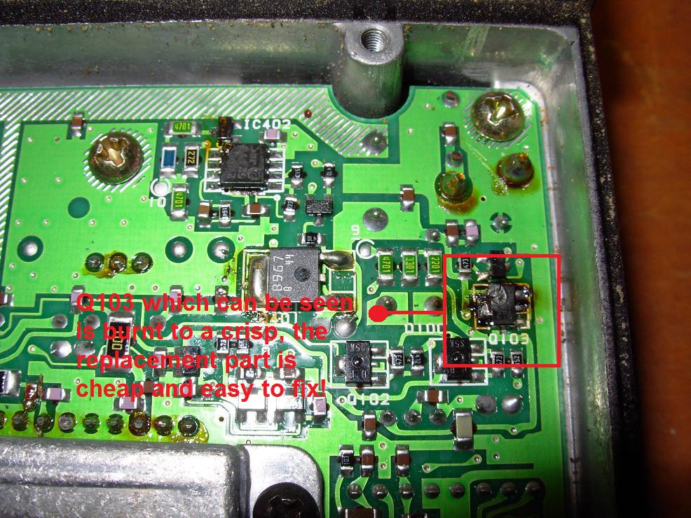
Q103 is a DC switching transistor and the original part number is 2SB1302S (2SB1302S Datasheet), this part is no longer manufactured, but a drop in replacement, part number 2SB1386 (2SB1386 Datasheet) is readily available from Mouser Electronics and cheap! I will mention that depending on how new/old your TK-931 is Q103 may be positioned differently i.e. oriented in a different direction, but in the same general spot. Simply remove Q103 (the crispy one) and install your new 2SB1386 transistor in its place, its a good idea before changing out the burnt Q103 is to check with a VOM that Pin 7 on the rear Molex connector is NOT GROUNDED!
“Help! I cannot create a working program file (.B90 file) for my TK-931 15 Watt Numeric only display radio.”
Kenwood Burn has an issue creating a new (.B90) program file from scratch. Kenwood Burn will create a new file but there will be no frequency data in the file and when you write it to your TK-931 it will not TX or RX. Fear not, there is an easy work around, you can either create a new program file in KPG-5D or you can download the template file found below and use that to create a new program file for your 15 Watt Non-alpha display TK-931. The template that is provided below has 1 System and 1 Group programmed with a frequency of 927.0125 and a 25MHz offset, the scan add/del feature has been enabled in this file so the "AUX SWITCH" dropbox in Kenwood Burn should be left alone. This program file issue in Kenwood Burn DOES NOT pertain to the TK-931D/HD.
TK-931 15 Watt Non-Alpha Display .B90 Template File
"Help! My 30 Watt TK-931HD has low RF power output.”
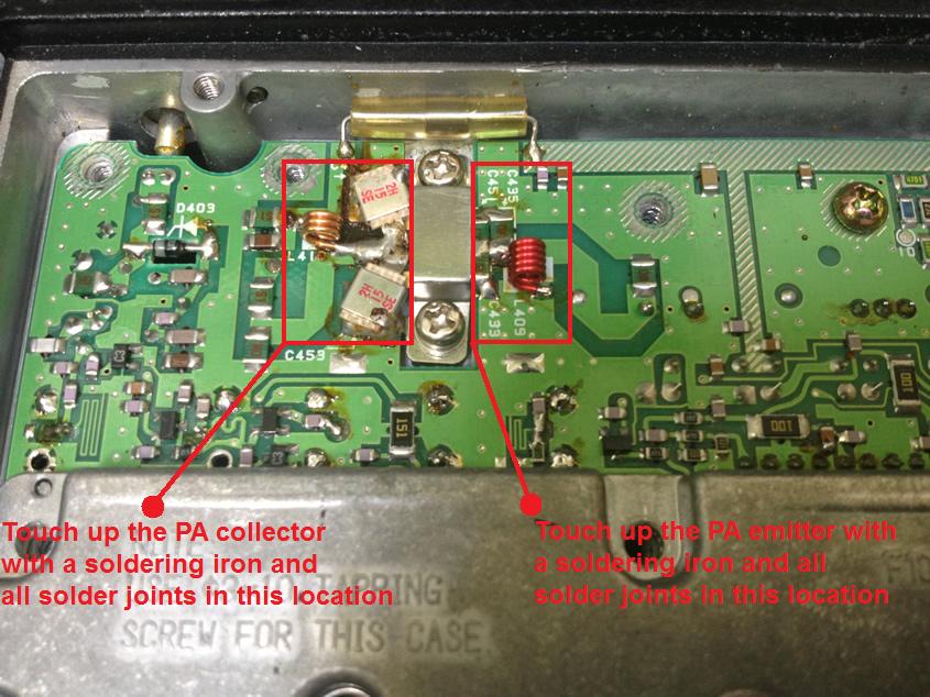
If your TK-931HD 30W radio has low power output (low, but not totally zero RF output) and you have tried adjusting the power output potentiometer (VR400) then there may be an easy fix. The PA final transistor (MRF847) has a pair of capacitors on its output along with an inductor, these components can de-solder themselves along with the PA collector under very heavy duty cycle due to heating in this area- this is not very common but it does happen. The easy fix for low power output is to re-flow the solder joints on the collector output of the PA, it's also a good idea to touch up the solder joints on the PA emitter as well. After you have touched up the solder joints on the PA be sure to re-check the power output of the TK-931HD and adjust it (using VR400) for 30 Watts at 902.xxxxMHz into a 50 Ohm dummy load.
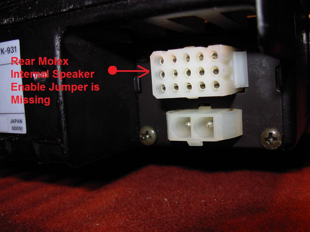
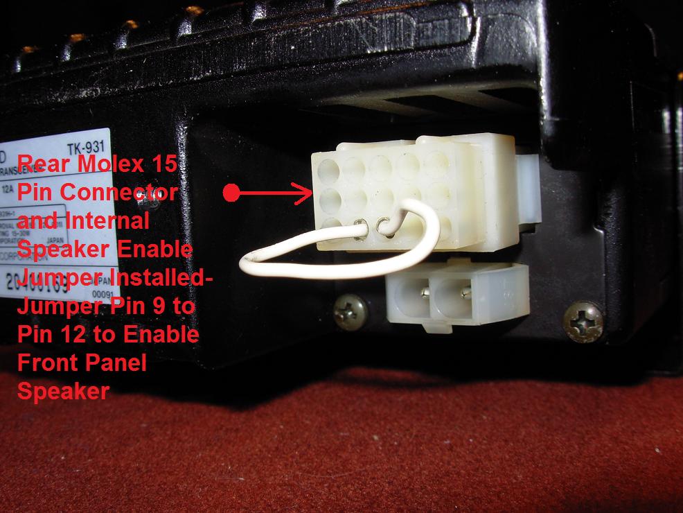
“Help! My radio has no audio through the front speaker.”
Assuming that the radio audio amp is not damaged and that the speaker is connected to the front panel in the display a quick check to see why you have no audio coming through the front speaker is checking the rear Molex connector. On the rear of the radio there is a 15 pin Molex connector, to enable the internal speaker in the front panel there should be a jumper from pin 9 to pin 12. If there is no Molex connector on back or there is no jumper from pin 9 to pin 12 then you must install one to enable the internal speaker- see images below for further details. The Molex connector 15 pin plug that fits into the receptacle on the back of the radio can be NO LONGER be ordered from Digikey as they are discontinued by Molex. This 15 pin Molex connector uses 0.062" male pins, which are Digikey part number WM3680CT-ND.
Molex Inc. TK-931 15 Pin Connector Datasheet
Molex Inc. TK-931 0.062" Male Pin Datasheet
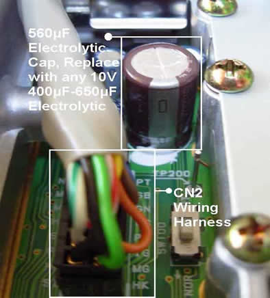
“Help! My radio makes a horrible noise through the front speaker.”
The most likely cause of a motorboat or feedback squealing sound coming through the front speaker is a failed electrolytic capacitor. Capacitor C117 is a 10 Volt; 560μF electrolytic capacitor located directly near the large gray CN2 wiring harness. When this capacitor goes bad the result is straight DC being passed on to the muting transistor, the speaker might be hot, and a horrible noise being admitted. You can replace the failed capacitor with any 10V or greater, 400μF-650μF electrolytic capacitor.
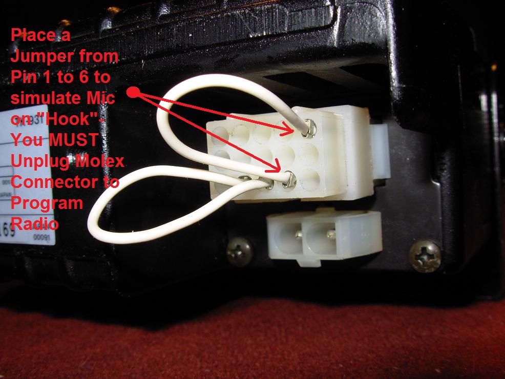
“Help! My radio will not scan.”
The reason that the radio will not scan is that the microphone must be on hook, i.e. the rear of the microphone must be grounded; hung up on a grounded microphone clip. The microphone being off hook will inhibit tone squelch (radio goes into carrier squelch) and inhibit the radio from scanning. You can either use a grounded microphone clip (preferred method) or there is a way to simulate the microphone being hung up “on-hook” . To get around this, i.e. simulate the microphone being on hook, the easiest thing to do is to connect a jumper from pin 1 (Hook) to pin 6 (ground) on the rear 15 pin Molex connector. The rear 15 pin Molex connector uses 0.062" male pins, which are Digikey part number WM3680CT-ND. Putting a jumper between these two pins will force the radio in tone squelch mode all the time- if tone squelch decode is programmed, and will also allow the scan function to work BUT when you go to program the radio you MUST disconnect the Molex plug from the radio, program the radio, then reinsert the Molex plug.
Molex Inc. TK-931 15 Pin Connector Datasheet
Molex Inc. TK-931 0.062" Male Pin Datasheet
“Help! My radio Scan Add/Delete function does not work.”
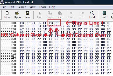
I would like to preface what I am about to say with praise for Kenwood Burn. It is an outstanding program, which I am sure took an enormous amount of time to perfect. The program allows easy programming of the TK-931’s and is a huge aid to the amateur radio 900MHz community. There is but one problem; the Scan Add/Delete function does not work. The way to get it to function involves Hex editing the saved programming file. Using the Hex editor of your choice (many are freeware, I use the program “HexEdit”) open the saved *.B90 or *.F90 file- the one you have programmed in your radio. On the first line (row) the sixth column over should read “FD”. On the first line (row) the seventh column over should be changed to “FF”. Save your changes in your Hex editor program and rewrite the program to the radio. Now that Scan Add/Delete works you will get a triangle ( › ) when the “A” button is pushed indicating that whatever System is selected will be skipped during scanning.
Shown Below is a saved .F90 file (TK-931D/HD) with the HEX Code that will enable- Scan Add/Delete. Program the "A" button for what ever you want and then using the Hex editor of your choice make sure the 6th column over reads "FD" and the 7th column over reads "FF"- see image below.
If you are not one for Hex editing then offered below are hex edited files for download. These .B90 and .F90 files have been edited for the Scan Add/Del feature on the "A" button.
TK-931 15 Watt Non-Alpha Display .B90 Template File
TK-931D/HD 15 or 30 Watt Alpha-Numeric Display .F90 Template File