Kenwood TK-941 for Repeater Use
The TK-941 has a fixed -39MHz offset and is clumsy to say the least in a mobile application. Since the TK-941 is not of much use for mobile amateur applications, it does work very well when used in building amateur repeaters. The TK-941's make outstanding link radios, exciters, and repeater receivers with little modification. What I like most about using the TK-941 is that they are front panel tunable; meaning you do not need a computer to adjust the max deviation, tone deviation, frequency, etc. to use this feature you must enable it in the software- this is really handy if you need to change or adjust a value and you're high on a mountaintop!
The TK-941 as a Repeater Receiver
The VCO of the TK-941 is adjustable and can be easily adjusted to work in any part of the 902-928MHz band. The RX filters will need to be changed out- this holds true for ANY 900MHz radio (Kenwood, Motorola, GE, or EF Johnson) if you want to receive at 902.xxxxMHz. Removing the filters is best done using hot air. Hot air has long been a standard for work with SMD applications and it works really well for removal of the filters in the TK-941 and TK-981.
To Program the TK-941 as a repeater receiver using KPG-25D:
- Run the DOS based Program KPG-25D
- Choose TK-941 from the "Model" Menu
- Program the desired 902.xxxxMHz frequency by selecting the corresponding FCC ID found in KwID.exe or the FCC ID to frequency Chart- so for example 927.5000MHz would be FCC ID #40 and after KW900EZP.exe is run will be 902.5000MHz.
- Be sure to leave "TXinh" and "TlkArnd" in the program set to "NO"- this is because of how KW900EZP.exe works, anything with Talk Around and Transmit Inhibit" Disabled will be a 902.xxxxMHz frequency.
- Save the file and run KW900EZP.exe and then reopen the saved file in KPG-25D.
- Make sure that you set "TXinh", Transmit Inhibit to "YES" then resave the file and double check using a Kenwood Microphone that PTT is inhibited.
- Using a service monitor or signal generator inject a signal at your 902.xxxxMHz frequency and adjust TC51 until the receiver opens up- ensure that you have 1.0Vdc or greater at test point "CV" with your RX frequency of 902.xxxxMHz. Test point "CV" is a test pad located near the RX filters.
Below is the step by step process for programming a 902.xxxxMHz frequency for your repeater receiver using the Hex edit method:
- Run the DOS based program KPG-25D.
- Choose TK-941 from the "Model" menu
- Program an FCC ID of 40 (935.5000MHz) in the FCC ID section in SYSTEM 1 GROUP 1 then add the QT/DQT (PL/DPL) frequency, be sure to ENABLE TRANSMIT INHIBIT! Save the file in the default directory and exit out of KPG-25D.
- To get a 902.xxxMHz receive frequency you will have to Hex edit the saved .910 file (the file saved by KPG-25D).
- Using the Hex editior of your choice open the saved .910 file and if you look closely at line 110 in the saved .910 file at the 8th and 9th column over, this is the receive frequency. If you programmed the radio with FCC ID 40 then this Hex should be "68" and next to it "9A". Change this Hex to your desired value using the chart below.
| Frequency | Hex | Frequency | Hex |
| 902.0125 | F1 8F | 902.2625 | 05 90 |
| 902.0250 | F2 8F | 902.2750 | 06 90 |
| 902.0375 | F3 8F | 902.2875 | 07 90 |
| 902.0500 | F4 8F | 902.3000 | 08 90 |
| 902.0625 | F5 8F | 902.3125 | 09 90 |
| 902.0750 | F6 8F | 902.3250 | 0A 90 |
| 902.0875 | F7 8F | 902.3375 | 0B 90 |
| 902.1000 | F8 8F | 902.3500 | 0C 90 |
| 902.1125 | F9 8F | 902.3625 | 0D 90 |
| 902.1250 | FA 8F | 902.3750 | 0E 90 |
| 902.1375 | FB 8F | 902.3875 | 0F 90 |
| 902.1500 | FC 8F | 902.4000 | 10 90 |
| 902.1625 | FD 8F | 902.4125 | 11 90 |
| 902.1750 | FE 8F | 902.4250 | 12 90 |
| 902.1875 | FF 8F | 902.4375 | 13 90 |
| 902.2000 | 00 90 | 902.4500 | 14 90 |
| 902.2125 | 01 90 | 902.4625 | 15 90 |
| 902.2250 | 02 90 | 902.4750 | 16 90 |
| 902.2375 | 03 90 | 902.4875 | 17 90 |
| 902.2500 | 04 90 | 902.5000 | 18 90 |
| Frequency | Hex | Frequency | Hex |
| 902.5125 | 19 90 | 902.7625 | 2D 90 |
| 902.5250 | 1A 90 | 902.7750 | 2E 90 |
| 902.5375 | 1B 90 | 902.7875 | 2F 90 |
| 902.5500 | 1C 90 | 902.8000 | 30 90 |
| 902.5625 | 1D 90 | 902.8125 | 31 90 |
| 902.5750 | 1E 90 | 902.8250 | 32 90 |
| 902.5875 | 1F 90 | 902.8375 | 33 90 |
| 902.6000 | 20 90 | 902.8500 | 34 90 |
| 902.6125 | 21 90 | 902.8625 | 35 90 |
| 902.6250 | 22 90 | 902.8750 | 36 90 |
| 902.6375 | 23 90 | 902.8875 | 37 90 |
| 902.6500 | 24 90 | 902.9000 | 38 90 |
| 902.6625 | 25 90 | 902.9125 | 39 90 |
| 902.6750 | 26 90 | 902.9250 | 3A 90 |
| 902.6875 | 27 90 | 902.9375 | 3B 90 |
| 902.7000 | 28 90 | 902.9500 | 3C 90 |
| 902.7125 | 29 90 | 902.9625 | 3D 90 |
| 902.7250 | 2A 90 | 902.9750 | 3E 90 |
| 902.7375 | 2B 90 | 902.9875 | 3F 90 |
| 902.7500 | 2C 90 |
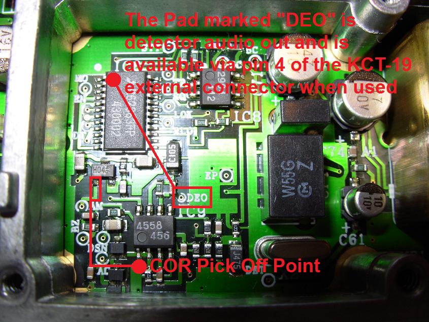
The pick off points for COR and low level, filtered audio.
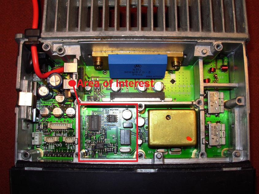
De-emphasized receiver audio and COR can be found at the locations pictured below.
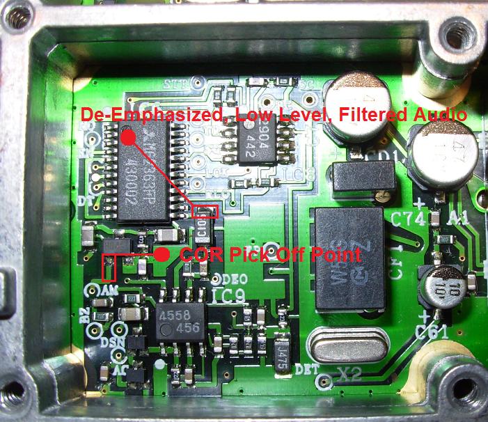
Pre-emphasized, detector audio is available via pin 4 of the 15-pin KCT-19 Molex connector when used and is a painless quick easy way of connecting your repeater controller to pre-emphasized, detector audio out. Detector audio is also marked on the main board as "DEO" (as pictured below) which is common with pin 1 of CN1 (8-pin SMD connector on the top side of the main board that the KCT-19 plugs into)- either of these points could be used if you prefer to wire directly to "DEO" and not use the KCT-19 external accessory connector. If you would prefer to build your own KCT-19 cables see the TK-941 "Tips and Modifications" section
for all needed part numbers.
The TK-941 as a Repeater Exciter
The TK-941 makes an ideal exciter for repeater use since they don't make very good amateur mobile radios due to the fixed offset. To program the radio for a 927.xxxxMHz Repeater Output frequency you can program it using KPG-25D and KW900EZP.exe or you can Hex edit the frequency.
To Program a TK-941 for a 927.xxxxMHz transmit frequency:
- Run the DOS based Program KPG-25D
- Choose TK-941 from the "Model" Menu
- Program the desired 927.xxxxMHz frequency by selecting the corresponding FCC ID found in KwID.exe or the FCC ID to frequency Chart- so for example 927.5000MHz would be FCC ID #40.
- Set the desired Time Out Timer time to 10 minutes and set all other settings as desired.
- Be sure to set "TlkArnd" in the program to "YES"- this is because of how KW900EZP.exe works, anything with Talk Around enabled will be a 927.xxxxMHz frequency.
- Save the file and run KW900EZP.exe and then reopen your saved file in KPG-25D, ensure that the desired transmit frequency is showing, adjust all settings in Test Mode such as max deviation, tone deviation, power out, etc...
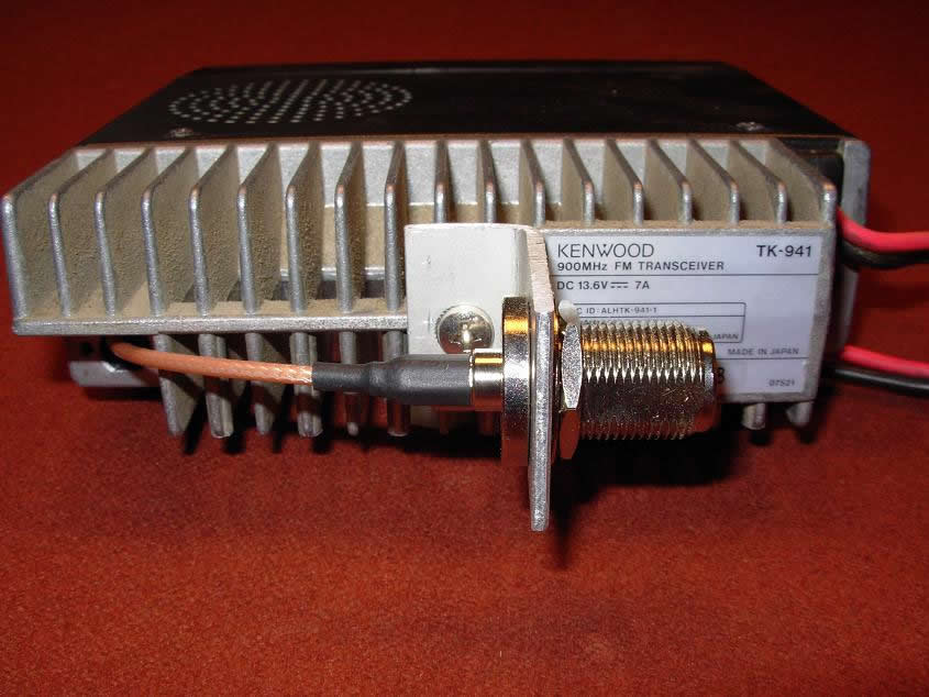
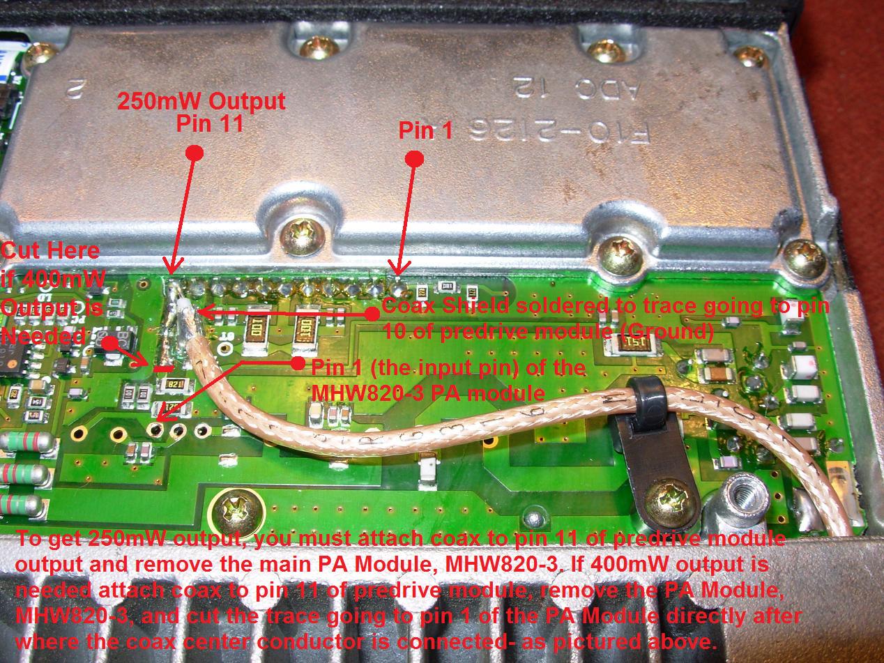
The TK-941 can be configured to run as a very low power (250 to 400mW Output) exciter or as 4-8 Watt exciter depending on what amplifer is being used. To get 250mW output you must remove the MHW820-3 PA module (often called the "Blue Brick") and solder a small length of RG-316 coax to pin 11 of the pre-drive module M57781, connect the RG-316 coax shield to the trace going to pin 10 of the predrive module which is ground. Pictured below is a TK-941 set up for 250mW output. A small pigtail is fed out the back of the radio using a small length of RG-316 with chassis mount N-connector.
To get 400mW output from the predrive module, M57781, you connect your coax the same way as mentioned above but cut the trace before the resistor network going to pin 1 (the input pin) to the PA Module (MHW-820-3). This network of resistors are a attenuator PI network and they drop the power output of the predrive module before it gets to the PA module, MHW820-3.
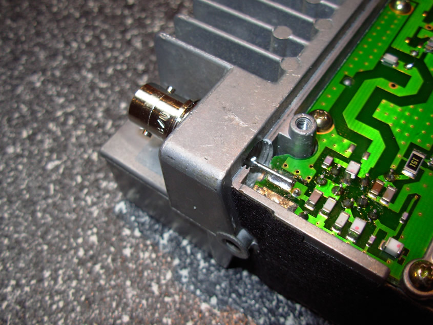
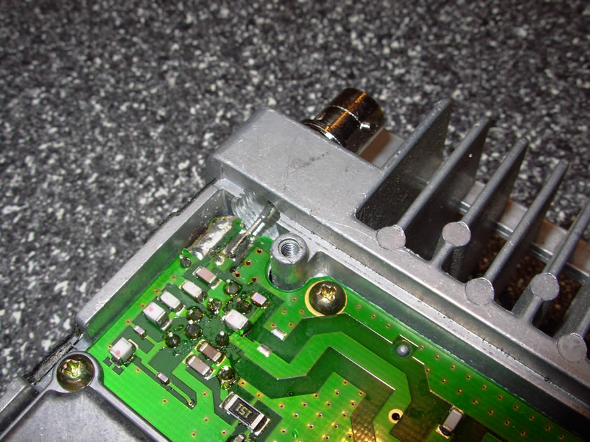
The TK-941 With Chassis Mount BNC Connectors
The TK-941 can have direct chassis mounted BNC connectors added very easily! If you want to use a TK-941 with a chassis mount BNC connector you can modify the chassis to accept one and depending on whether you are using the TK-941 as a repeater receiver, exciter, or low power exciter it will require minor changes to the board. The most difficult step is acquiring a 3/8" x 32 tap- these are not easy to find, but you will need one because most/all chassis mount BNC connectors have 3/8" x 32 UNEF threads; eBay is probably the cheapest and easiest place to find these taps.
You will need the following items:
- 3/8" x 32 Thread Pitch Starter Tap (Finishing/Bottoming Tap Optional)
- 11/32" Drill Bit (For Above Mentioned Tap)
- Countersink Drill Bit
BEFORE WE START:
Make sure that you understand that this modification is NOT for people who lack an understanding of how to work with hand tools, small parts, or fabrication. Know YOUR limitations and don't try to do this modification if it is beyond your current skill level. YOU HAVE BEEN WARNED!
- I am going to skip all the pictures involved with disassembling the radio. As an added note if disassembly of your TK-941 is terribly difficult for you, then stop, this project is definitely not for you! We need to remove the top and bottom cabinet covers of the radio, and also remove the speaker, front panel with LCD display. Removal of the front panel with LCD display will require you to unplug the ribbon cable from the control board; the board with the mic connector on it which is mounted to the front of the radio chassis. Removal of the control board on the front of the radio will require you to unplug the ribbon cable which is connected to the front bottom of the main RF board- be very careful in doing this! We also want to remove the retainer clip that holds the audio PA securely to the chassis, and remove the retainer clip that holds the 7808 voltage regulator and APC drive transistor to the TK-941 chassis. Flip the radio over and remove the RF shield that covers the bottom of the main RF board on the radio. We also want to remove the 2 screws holding the coax pigtail to the rear of the chassis and de-solder the coax pigtail and remove it, be careful in doing this, as too much heat can remove the trace from the main board. Save all screws you have removed and keep track of what screws went where; we will be re-using them in this project.
You will need to remove the 2 screws that hold the PA module (Motorola MHW820-3) to the rear heatsink. After removing the PA screws remove all screws holding the main RF board to the chassis and save. Carefully and slowly remove the main RF board from the chassis. Clamp the bare chassis in a vise and have it positioned as shown.
- Using the countersink bit chamfer the hole in the chassis where the coax previously penetrated the chassis of the radio. You will need to chamfer the edge so that the boss on the chassis mount BNC has enough clearance to sit flush with the chassis of the radio. After using the countersink bit to chamfer the edge of the coax penetration use the 11/32" drill bit to drill out the chassis where we just chamfered the edge- be sure to drill in the center of the hole!
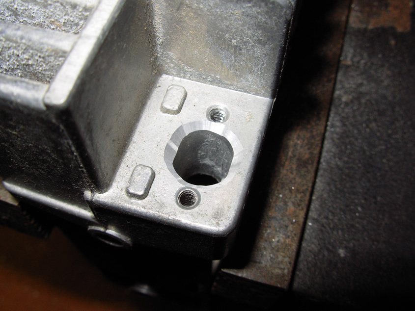
- Now that the hole in the chassis is the proper size we can tap the chassis to accept the BNC chassis mount connector. Use the 3/8 x 32 UNEF tap and ensure the tap is properly centered. The chassis material is very soft so you will not need to add any oil. The threads should be clean and as pictured below.
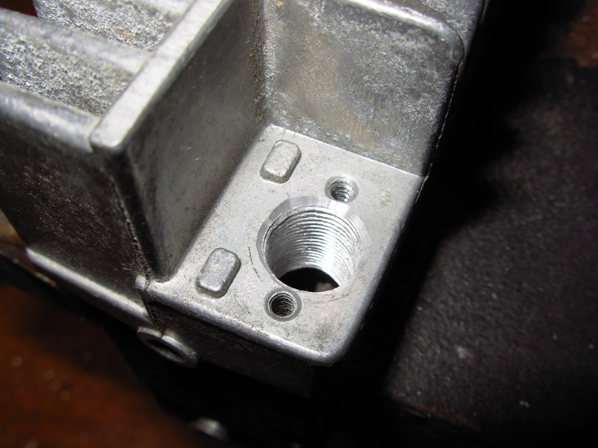
- Now that the chassis has been threaded we can test fit the chassis mount BNC connector. If the connector does not sit flush then you will need to countersink the chassis a little more with the countersink bit we used in step 2- if you need to countersink the edge more use caution as to not damage the threads!
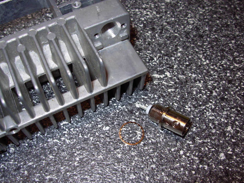
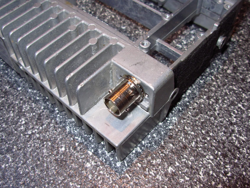
- At this step you will do a couple different steps depending on what you are doing with the radio. If the radio is going to be a repeater receiver and the filters have been changed then you can reassemble the radio, if the radio is going to be an exciter you can reassemble the radio and at this point it may be a good idea to apply fresh thermal compound to the PA module. Shown below is a repeater receiver and/or exciter with a jumper installed to bridge the gap of the center conductor to the board. SKIP AHEAD to step 6 if you are building a low power exciter (mW out).
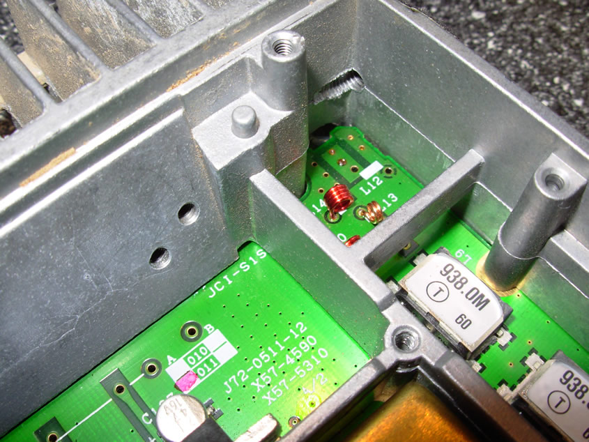
- If you are building a low power exciter (mW out) then you have a few extra steps to do. By this step you will need to have removed the MHW820-3 PA module (often called the "Blue Brick"), you will also need a short length of RG-316 to jumper the predrive module, M57781, to the center pin of the chassis mount BNC connector. Please see the "The TK-941 as a Repeater Exciter" section above for the "how-to" on setting this low power exciter up.


- For the final step of the low power exciter (mW out) you will need to remove the L12 coil from the top side of the board, it may not be necessary to do this, but I thought it was a good idea to do so. You are now finished and can test out your new BNC converted TK-941!
TK-941 Time Out Timer (TOT) Disable Circuit
The TK-941 has a built in Time Out Timer (TOT) that can be programmed in 15 second increments from 15 to 600 seconds to turn off the radios transmitter if the programmed transmit time is exceeded. The TOT is a desired function when the radio is used in a mobile or fixed station environment. However, the TOT feature is not desirable when using the radio as a repeater exciter with an external repeater controller managing the transmitter time out function. The one problem of the TK-941 TOT function is that it cannot be disabled in the programming software; KPG-25D.
Greg, WB6ZSU came up with a TOT disable circuit for the TK-931 some years back. Greg's TOT disable circuit was simple and worked well, as the TOT disable circuit that Greg came up with does not actually disable the TOT on the TK-931, it just resets the TOT timer very, very quickly by disabling the transmitter for a few mS. After using this timer on my first repeater consisting of TK-931's I know it worked flawlessly and it was very hard to notice the transmitter drop out due to how quickly it happened when listening to the repeater. It occurred to me one day that the TK-931 TOT disable circuit must be able to be retrofitted on the TK-941.
In a recent correspondence via email with John, W3RC, he mentioned that he had used a version of Greg's TK-931 TOT on his TK-941 based repeater- we later exchanged a couple notes and out came this circuit, a modified version of WB6ZSU's original TK-931 TOT disable circuit.
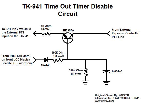
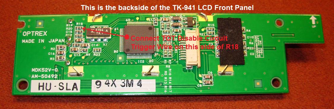
There are 3 connections to make when installing this TOT disable circuit in the TK-941. The board is inserted in-line with the controller PTT line to the radio. If you are using a KCT-19 cable on your TK-941 for interfacing to a repeater controller you will need to cut the purple wire approximately 1" away from where it is connected to CN1 Pin 7; External PTT. This 1" length of purple wire will connect to the 1/8 Watt 1K Ohm resistor, the other end of the purple wire that goes out to the 15 pin Molex will connect to the collector of the 2N2907A (2N2907A Datasheet). The last connection is the trigger wire, that wire will connect to the inboard side (the side towards the middle of the board) of R18, a 4.7k Ohm SMD resistor on the front LCD panel, please see the picture below.
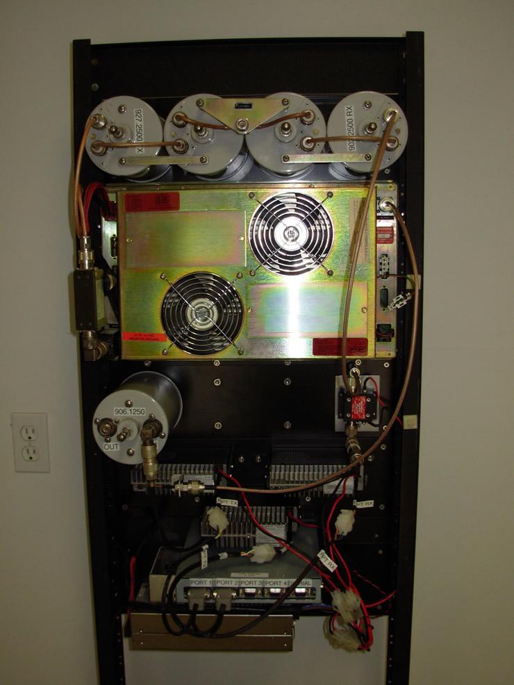
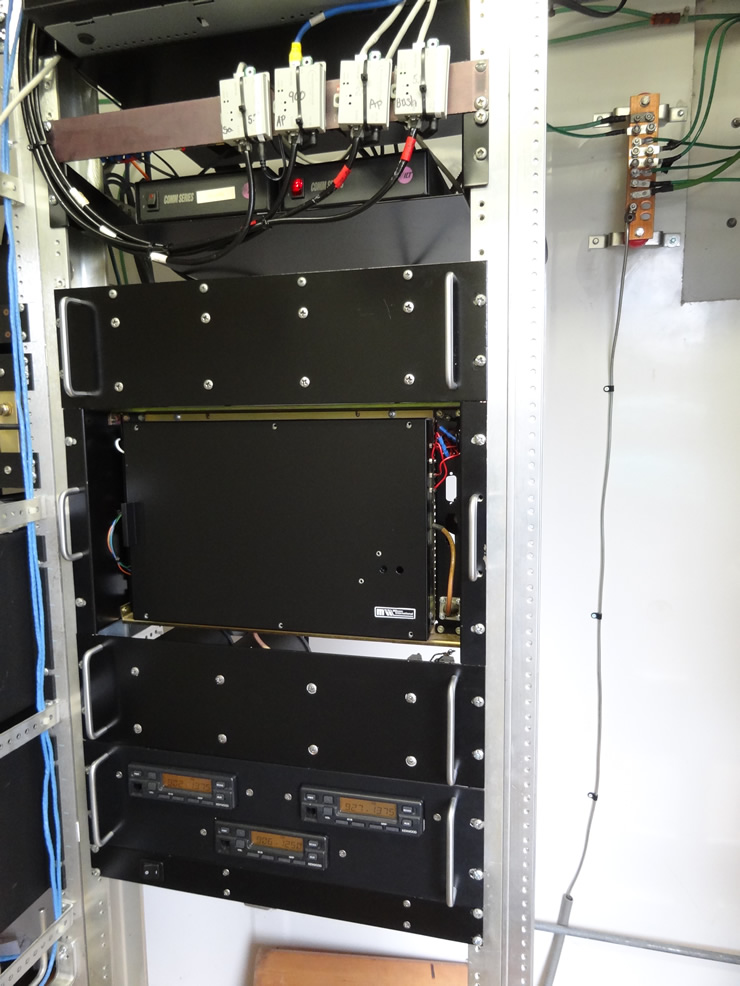
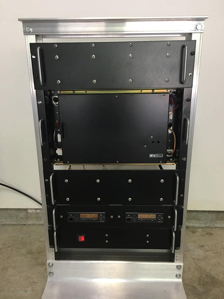
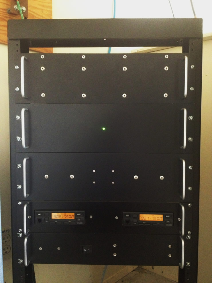
TK-941 Repeaters in Service
KD6VPH Baw Faw, WA Repeater, 927.9250MHz QT 114.8Hz
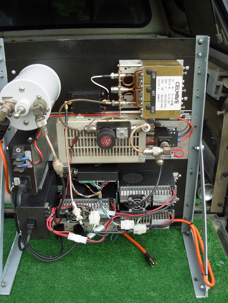
2 TK-941L Link Radios, 350mW Exciter, Milcom 150W 900MHz Amplifier running 90W output,
Wacom WP-688 Duplexer
KD6VPH South Mt., WA Repeater, 927.2500MHz QT 114.8Hz
TK-941L Link Radio, 350mW Exciter, Milcom 150W 800MHz converted to 900MHz Amplifier running 90W output, Wacom WP-688 Duplexer
KD6VPH Maxwell Hill, WA Repeater, 927.1375MHz QT 131.8Hz
TK-941L Link Radio, 350mW Exciter, Milcom 80W 800MHz converted to 900MHz Amplifier running 80W output, Wacom WP-688 Duplexer
KD6VPH Shelton, WA Repeater, 927.4125MHz QT 114.8Hz
350mW Exciter, Milcom 80W 800MHz converted to 900MHz Amplifier running 80W output, Wacom WP-688 Duplexer

KD6VPH Bush Mt., WA Repeater, 927.7500MHz QT 114.8Hz
350mW Exciter, Milcom 50W 800MHz converted to 900MHz Amplifier running 45W output, Wacom WP-688 Duplexer
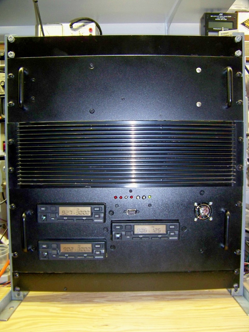
W7UVH Semi-Portable Repeater, 927.3000MHz QT 114.8Hz
10W TK-941 Link, 8W Exciter, TPL 30W 900MHz Amplifier, Celwave Notch Duplexer