Kenwood TK-981 Filter Changeout
The TK-981 does not need the existing receive filters centered at 938MHz changed out for use at 927Mhz. These filters are rather broad banded, little improvement can be gained by changing them but a good reason to change them out is mainly for the people in New England and other regions of the East Coast that still use the 12MHz repeater offsets.
The VCO in the TK-981 will do both 12MHz offset repeaters and 25MHz offset repeaters at the SAME time, or basically receive and talkaround (simplex) from 918MHz to 927MHz- something very few radios can do!
There are 2 ways to accomplish the change out of the receive filters on the TK-981 you can remove them while the RF board is still in place or if you have plans of converting your radio to a 30 Watt version then remove the filters at that time. The front end of the TK-981 contains 2 SMD filters which are 3 poles each. They are easy to remove using a hot air SMD re-work station, as you can remove the filters entirely with no-damage to the traces on the board in around 1 to 2 minutes. The filters are a lot more difficult to remove using a normal soldering iron. I have done both methods and the way to go is hot air. A good alternative to purchasing a hot air rework station is purchasing something you can use much more frequently, a butane powered soldering iron with the diffuser (nozzle) tip attachment, I have used the Master Appliance Iron model number UT-100SI with great results; do not use anything smaller than this as it does not provide enough heat. Another way to remove the SMD filters is using a high power iron in the 100W to 150W range, and heating and removing the filters section by section- this works but you have to be VERY patient and use a VERY HOT iron.
Pictured below is step by step disassembly as well as removal of the TK-981 receive filters using my Hakko 850 Hot Air station.
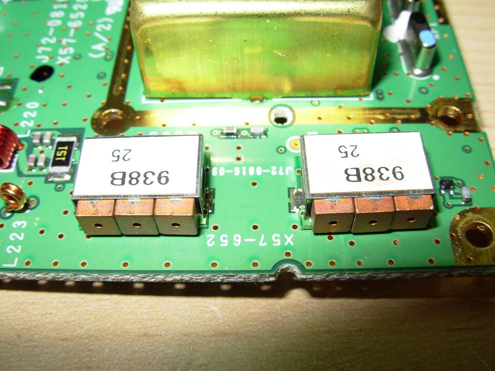
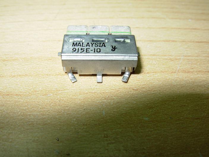
- Original TK-981 938MHz Receive Filters, 6MHz Bandwidth
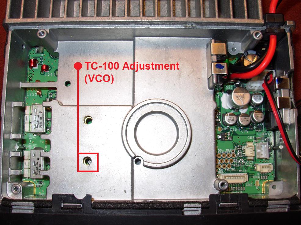
- TK-981 938MHz with Top Cover Removed

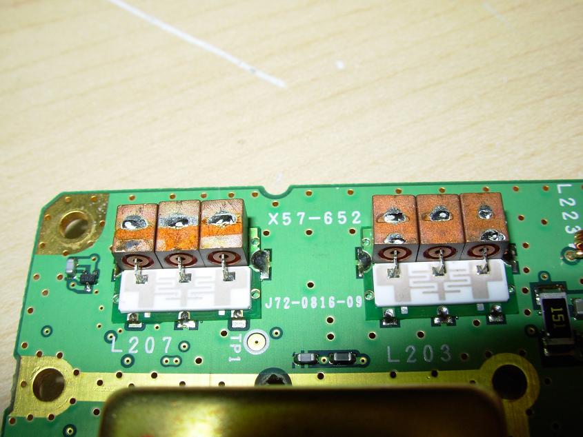
- TK-981 938MHz Filters with Tuned Stripline Circuit Boards
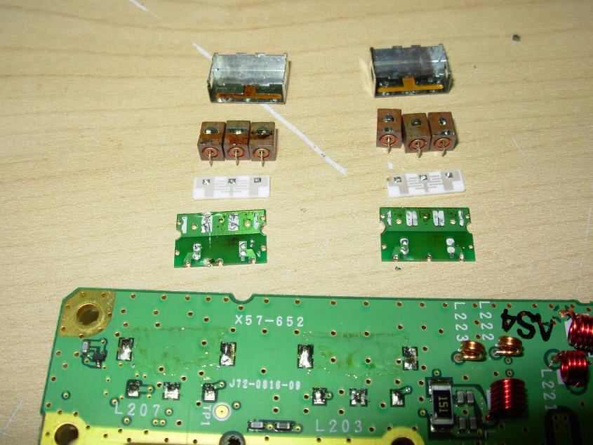
- TK-981 Ceramic Elements Removed

- TK-981 Ceramic Elements and Stripline Tuned Boards Removed

- TK-981 938MHz filters Completely Disassembled
- The Toko 4DFB-915E-10 SMD Filters are almost a drop in replacement, however, they are very hard to locate, I have used all sorts of different styles including thru-hole style filters, use your imagination here! If you do happen to find the Toko 4DFB-915E-10 filters you will need to bend the input and output pins slightly so that they fit properly. Also ensure that you ground the ground tabs on either side of the filter by scraping the coating off of the board and soldering the filter ground pins to the board. Proper grounding of these filters, and all bandpass filters in general, has a big impact on their proper function.
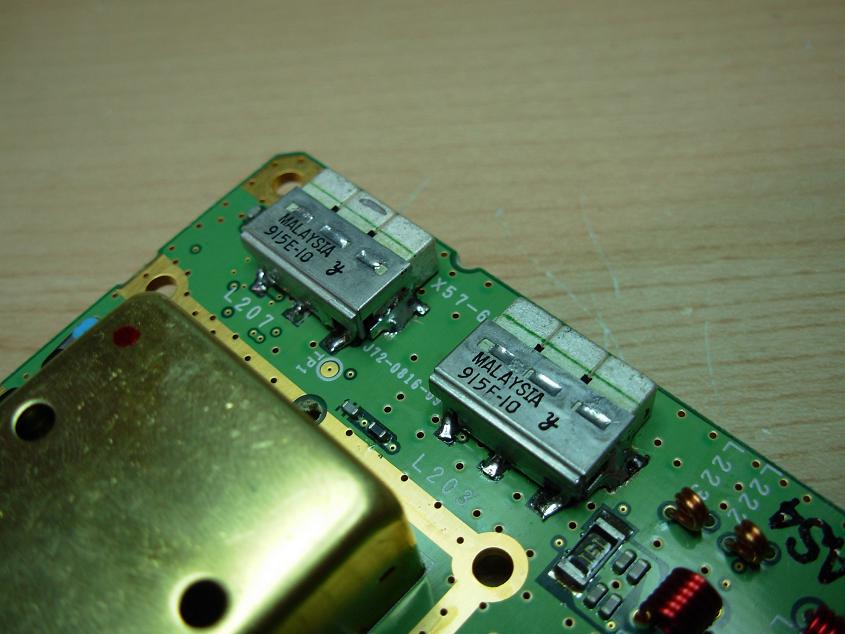
- TK-981 with Toko 4DFB-915E-10 SMD filters installed

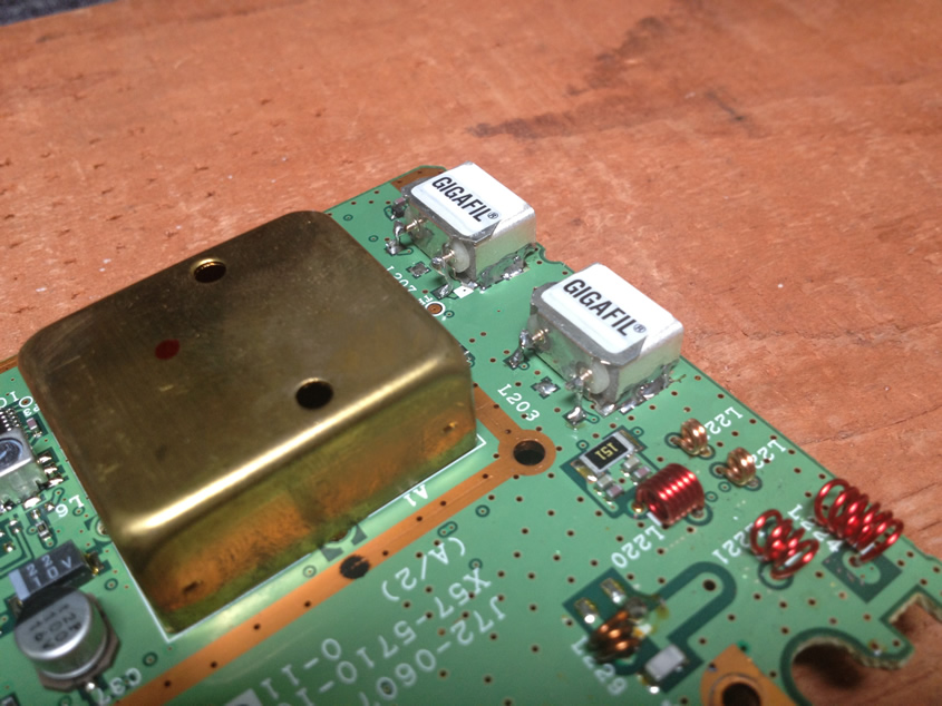
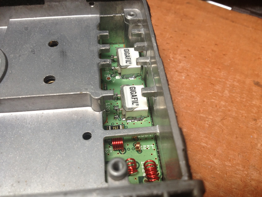
- TK-981 with muRata DFC2R915P025BTD Thru hole filters installed.
- To get the TK-981 to do both the 12MHz and 25MHz splits, you must readjust the VCO slightly. This is accomplished by programming in the below listed frequencies. You can program these frequencies in as test frequencies (see the "Tips and Modifications" TK-981 section for the how-to) so you can readjust the VCO in test mode OR you can create a .DAT file with the below listed frequencies by using Pete's Program, KW900EZP.exe and the EzEdit function- see the "Programming" and "Downloads" section for further details.
- 918.0000MHz/906.0000MHz
- 919.0000MHz/907.0000MHz
- 920.0000MHz/908.0000MHz
- 921.0000MHz/909.0000MHz
- 922.0000MHz/910.0000MHz
- 923.0000MHz/911.0000MHz
- 924.0000MHz/912.0000MHz
- 925.0000MHz/913.0000MHz
- 926.0000MHz/914.0000MHz
- 927.0125MHz/902.0125MHz
- 927.9875MHz/902.9875MHz
- Once the above frequencies are programmed in, using a service monitor or signal generator, generate a signal at 918.0000MHz, and using a ceramic tuning tool, adjust TC100 until the receiver opens up, in my experience doing this it usually takes a very, very small turn counterclockwise to get the VCO voltage where it needs to be. Then jump to 927.9875 and make sure you can receive as well. As a way to double check yourself, go through every receive frequency, and ensure you can receive it, you will most likely be able to receive everything above 918MHz because if you can hear 918.0000Mhz and 927.0000MHz then you are going to be able to hear everything in between, but its a good idea to check your work. Then disconnect your service monitor and try transmitting on every frequency from 914.0000MHz working your way down towards 902.0125MHz. If everything works then you are finished, if it doesn't work, then start back at the 918.0000MHz receive frequency and double-check that. If you haven't done this before then it can take a little patience, but the reward is worth it!